
System for controlling discharging of super capacitor by relay group
A supercapacitor and relay group technology, which is applied in the system field of relay group control supercapacitor discharge, can solve the problems of inability to test large current, short service life, inconvenient use, etc., and achieve simple structure, long service life, high current wide range of effects
Patent Information
- Authority / Receiving Office
- CN · China
- Patent Type
- Applications(China)
- Current Assignee / Owner
- Publication Date
- 2017-06-20
Smart Images
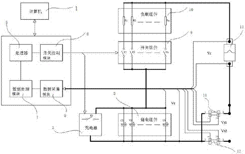
Figure 1
Abstract
Description
technical field
[0001] The invention relates to a system for controlling the discharge of a supercapacitor by a relay group. Background technique
[0002] At present, only foreign companies in the world can make circuit breaker test systems, but the products made by foreign companies cannot be tested for a long time, they only measure instantaneous data, and they cannot test high current conditions. Foreign products are expensive. , short service life and inconvenient to use. Contents of the invention
[0003] The technical problem to be solved by the present invention is to overcome the deficiencies of the prior art and provide a system for controlling the discharge of supercapacitors by a group of relays. , the advantages of high intelligence and low cost.
[0004] The technical scheme adopted in the present invention is:
[0005] A system for controlling the discharge of supercapacitors by a group of relays, which includes a computer, a control system communicatively...
Examples
Embodiment Construction
[0020] Such as figure 1 As shown, the system for controlling the discharge of a supercapacitor by a group of relays in the present invention includes a computer 1, a control system communicatively connected to the computer 1, a resistance adjustment module electrically connected to the control system, and a resistance adjustment module electrically connected and The connector electrically connected to the control system, the charger 2 electrically connected to the control system, the power storage component 3 electrically connected to the charger 2 and electrically connected to the control system, and the electric storage component 3 electrically connected to the control system and electrically connected to the connector Two shunts connected together.
[0021] The control system includes a processor 5, a switch control module 6 electrically connected to the processor 5, a data processing module 7 electrically connected to the processor 5, and a data acquisition module 8 electr...