
Wire winding device arranged between tin soldering power line core and varnished wire
A technology for power cords and enameled wires, applied in circuits, electrical components, cable/conductor manufacturing, etc., can solve problems such as soldering quality that affects the quality of wire wrapping, not very practical, tremor errors, etc., to achieve simple structure, simple control, and avoidance. The effect of virtual welding
Patent Information
- Authority / Receiving Office
- CN · China
- Patent Type
- Applications(China)
- Current Assignee / Owner
- Publication Date
- 2017-06-30
Smart Images
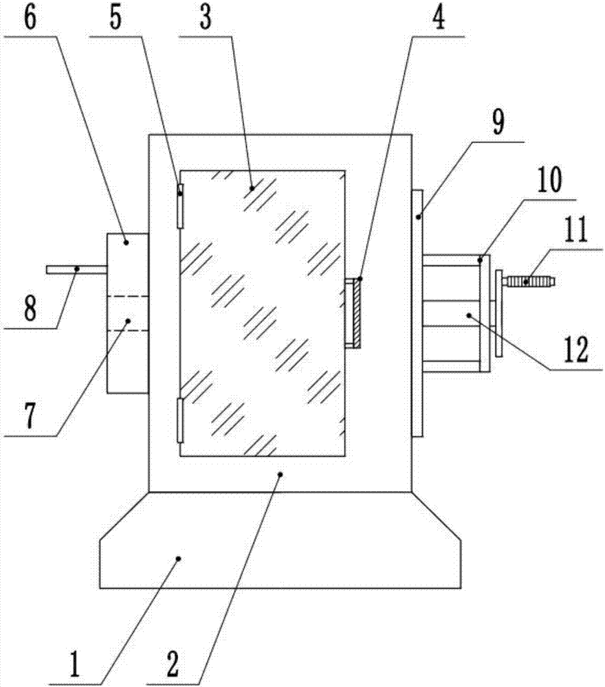
Figure 1 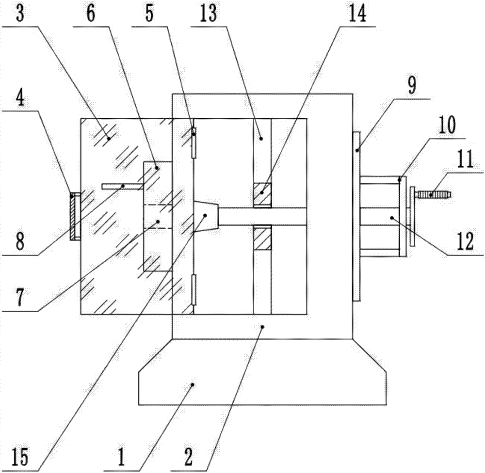
Figure 2 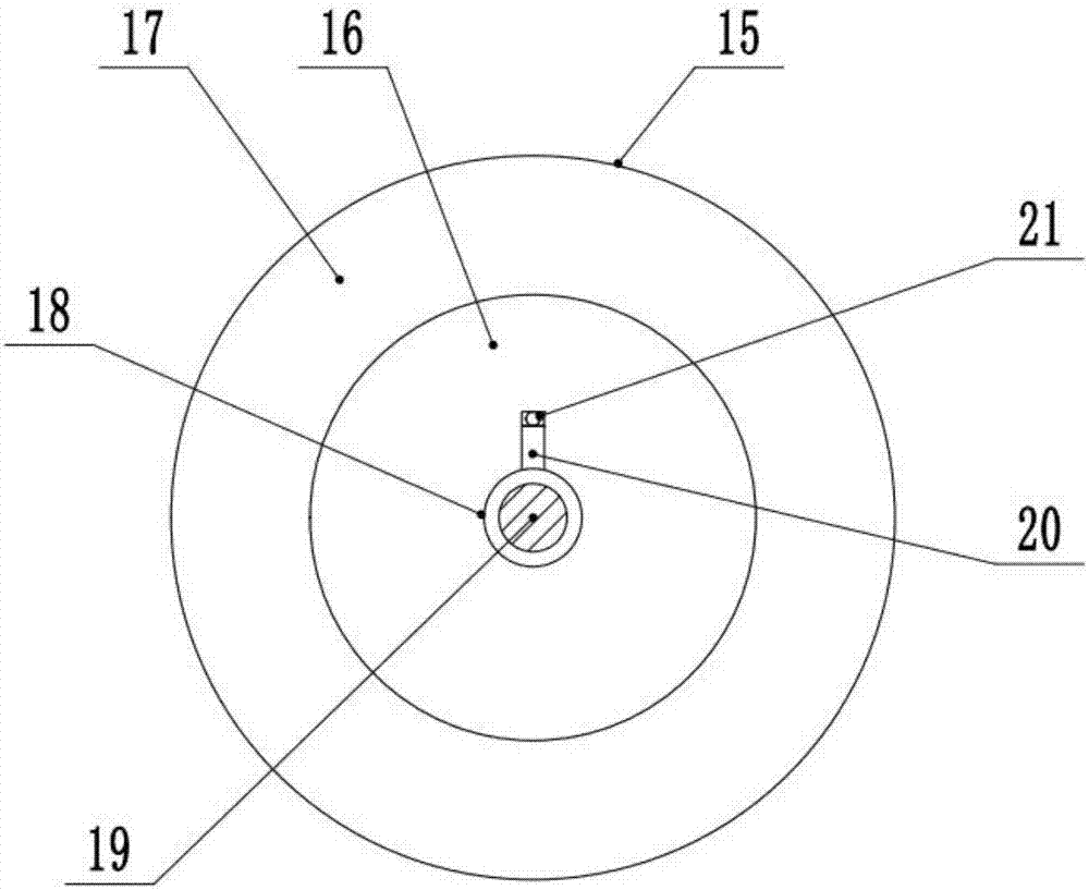
Figure 3
Abstract
Description
technical field
[0001] The invention relates to the field of mechanical processing, in particular to a wire winding device between a soldering power cord core and an enameled wire. Background technique
[0002] The wire winding machine is a kind of twisting mechanical equipment that can be widely used in various types of soft / hard conductor wires, so that multiple single conductors are twisted into one strand to meet the technical requirements of the wire. It is not very practical when it is used, because many of the ends of the power cord of the motor are soldered. superior.
[0003] At present, in the process of motor production and production, it is necessary to wrap the wire at the joint of the motor. When winding the wire, because many power cord ends of the motor are soldered, and the power cord after soldering is relatively hard. The winding operation can improve the quality of the winding wire and avoid false soldering during soldering before and after production. ...
Examples
Embodiment Construction
[0016] The technical solution of this patent will be further described in detail below in conjunction with specific embodiments.
[0017] see Figure 1-3 , a wire winding device for soldering between a power cord core and an enameled wire, comprising a device body, a base 1 is provided at the bottom of the device body, a housing 2 is provided above the base 1 , and the housing 2 and the base 1 are Fixedly connected by welding, the shell 2 is a hollow structure, the front of the shell 2 is provided with an observation window 3, and the observation window 3 and the shell 2 are rotatably connected by the function of the hinge 5, and the observation window 3 The handle 4 is set on the right side of the handle 4, and the handle 4 is fixedly connected with the observation window 3 through the action of the fixing screw, and the observation window 3 and the shell 2 are snapped and connected through the buckle, and the left side of the shell 2 A plug-in positioning plate 6 is arrange...