
Array antenna
An array antenna and array technology, applied in the field of communication, can solve the problems of increased antenna volume, low gain, and great influence of antenna units, and achieve the effects of narrowing the beam width, improving the front-to-back ratio, and realizing miniaturization
Patent Information
- Authority / Receiving Office
- CN · China
- Patent Type
- Applications(China)
- Current Assignee / Owner
- Publication Date
- 2017-11-17
Smart Images
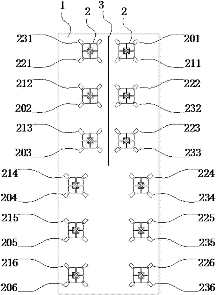
Figure 1 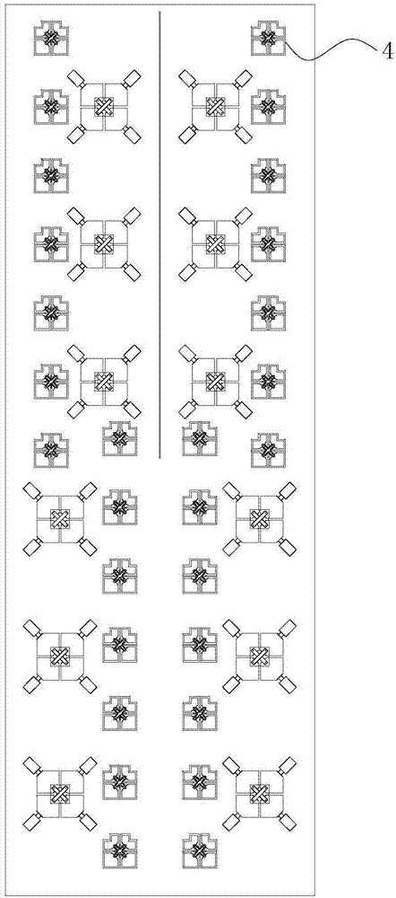
Figure 2 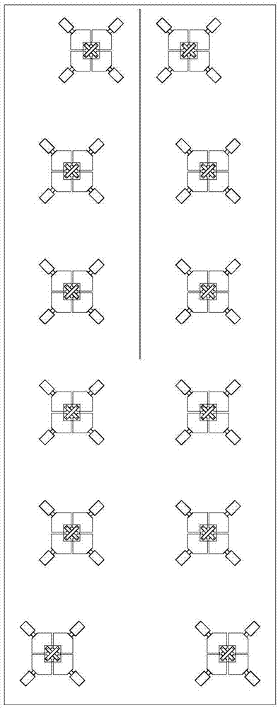
Figure 3
Abstract
Description
technical field
[0001] The invention relates to the communication field, in particular to an array antenna. Background technique
[0002] With the large-scale use of mobile intelligent terminals such as smartphones and tablet computers, as well as the astonishing growth of users of instant messaging software such as Facebook, WhatsApp, Twitter and WeChat, and the rapid development of wireless services such as mobile video, the data traffic of mobile communications Showing explosive growth, users put forward higher and higher requirements for the capacity of the communication system. On the other hand, as the difficulty of site construction increases, in order to reduce the cost of network construction, operators are required to achieve co-site and co-location. Therefore, multi-system, broadband and miniaturized base station antennas have become one of the current hot spots.
[0003] Currently, a common technical means for improving system capacity is to use a MIMO (Multiple...
Examples
Embodiment 1
[0027] Such as figure 1 As shown, an array antenna includes: a metal reflector 1, a partition wall 3 and two low-frequency sub-arrays 2, and the two low-frequency sub-arrays 2 are arranged on the metal reflector 1 alternately, and the partition wall 3 is arranged along the metal reflector 1. The center line of the reflector 1 is set, and each low-frequency sub-array is composed of the first group of low-frequency radiation units, the second group of low-frequency radiation units and the third group of low-frequency radiation units, and the first group of low-frequency radiation units is arranged on one side of the partition wall 3 , the second group of low-frequency radiation units and the third group of low-frequency radiation units are arranged on the other side of the partition wall 3, the second group of low-frequency radiation units are arranged on a straight line close to and parallel to the center line of the metal reflector 1, the third group The low-frequency radiatio...
Embodiment 2
[0033] Such as figure 2 As shown, the low-frequency array arrangement in this example is the same as that in Embodiment 1. The high-frequency radiation unit 4 includes two oscillators that are orthogonal to each other, and a plurality of high-frequency radiation units 4 are arranged in four straight lines parallel to the centerline of the metal reflector. Above, four high-frequency arrays are formed, from left to right are the first high-frequency array, the second high-frequency array, the third high-frequency array, and the fourth high-frequency array. Each high-frequency array is composed of seven high-frequency radiation unit composition.
[0034] Among them, the first and fourth high-frequency arrays are located outside the straight line where the second and third radiation units of the two low-frequency arrays are located, and the second and third high-frequency arrays are located where the fourth, fifth and sixth radiation units of the two low-frequency arrays are loca...
Embodiment 3
[0038] Such as image 3 As shown, the array antenna in this embodiment is basically the same as that in Embodiment 1, except that M=4 and N=1. The first radiating units of the two low-frequency sub-arrays are located between the straight lines where the second and third radiating units of the two low-frequency arrays are located.