
Engine idle speed control method and control device
A technology of engine idle speed and idle speed, which is applied in engine control, machine/engine, electrical control, etc., and can solve problems such as vehicle battery loss, failure to start, engine idling vibration or flameout, etc.
Patent Information
- Authority / Receiving Office
- CN · China
- Patent Type
- Patents(China)
- Current Assignee / Owner
- Publication Date
- 2020-05-01
Smart Images
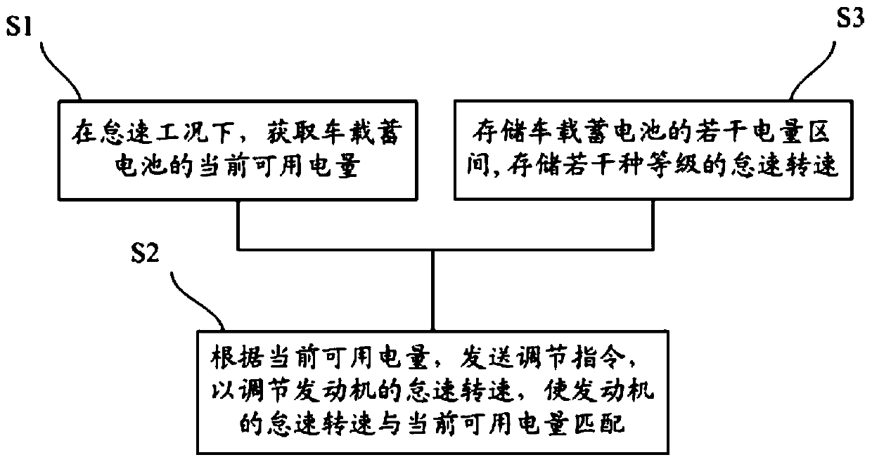
Figure 1 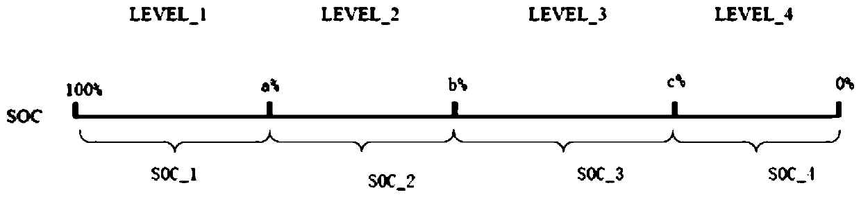
Figure 2 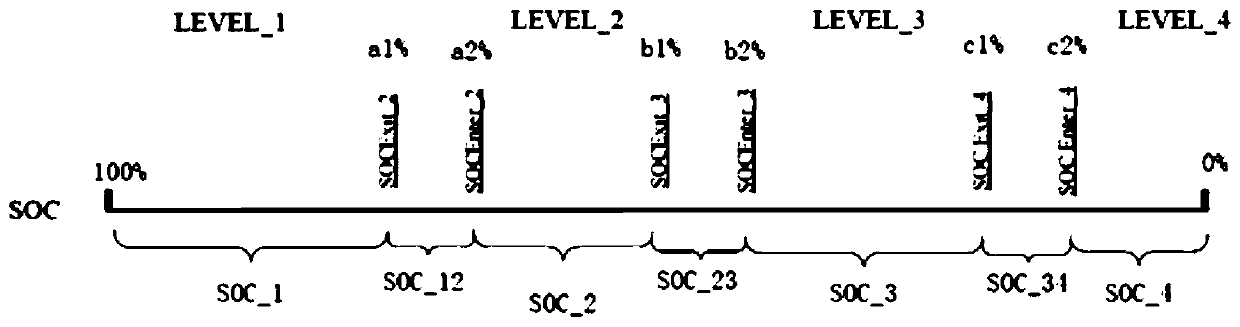
Figure 3
Abstract
Description
Technical field
[0001] The invention relates to the field of automobile control, in particular to a control method and a control device of an engine idling speed. Background technique
[0002] The idling condition of a car refers to the operating state when the accelerator pedal is completely relaxed and the engine is idling. Idling mode is one of the important working conditions of the engine, which is closely related to the emission level and energy consumption of the engine. Therefore, under the premise of meeting the increasingly stringent emission regulations, maintain the performance of various vehicle functions under the idling mode. Stability is very important.
[0003] The car is equipped with a generator, which is used to supply power to the vehicle load (ie, vehicle electrical equipment), or to store the generated electrical energy in the vehicle battery. The generator is connected to the engine, and the engine generates electricity. The speed and power generation effi...
Examples
no. 1 example
[0056] The embodiment of the present invention provides a method for controlling the idle speed of an engine, such as figure 1 As shown, including the following steps:
[0057] S1: Under idling conditions, obtain the current available power of the vehicle battery;
[0058] S2: According to the current available power, send an adjustment command to adjust the idle speed of the engine so that the idle speed of the engine matches the current available power;
[0059] Among them, the idling speed is inversely related to the current available power.
[0060] Since the generator and the vehicle engine are connected in transmission, the two have a certain speed ratio, and the on-board alternator is an approximate constant voltage source. Generally, the excitation current is controlled by a regulator to stabilize the output voltage at a certain value. The greater the vehicle load, the greater the output current required by the generator, but the maximum output current of the generator is dete...
no. 2 example
[0088] The difference between this embodiment and the first embodiment is that several power intervals are discontinuous, and there is an interval between two adjacent power intervals, and this interval is defined as a transition interval.
[0089] Such as image 3 , Select 100%, a1%, a2%, b1%, b2%, c1%, c2%, 0% as the critical points of each power interval, where 100%>a1%>a2%>b1%>b2%>c1 %>c2%>0%. The power range between 100% and a1% is the first power range SOC_1, the power range between a2% and b1% is the second power range SOC_2, and the power range is between b2% and c1%. It is the third power range SOC_2, and the range of the power range between c2% and 0% is the fourth power range SOC_4.
[0090] The power range between a1% and a2% is the first transition region SOC_12, the power range between b1% and b2% is the second transition region SOC_23, and the power range is between c1% and c2%. This is the third transition interval SOC_34. From image 3 It can be seen that the fi...
no. 3 example
[0129] The difference between this embodiment and the second embodiment is that the method of "determining the target level" in step S22 is different.
[0130] In this embodiment, the current available power p is first compared with the power interval corresponding to the idle speed one level lower, and if the result is no, then the current available power p is compared with the power interval corresponding to the idle speed one level higher. Compare and finally get the target level.
[0131] Specifically, combine Image 6 , The steps of step S22 "determine the target level" include:
[0132] S221: Obtain the current idling speed;
[0133] S222: Determine the current level corresponding to the current idle speed;
[0134] S223: Determine the electric power interval corresponding to the idle speed one level higher than the current level; determine the electric power interval corresponding to the idle speed one level lower than the current level;
[0135] S224: Determine whether the curre...