

Method for controlling impeller type yarn laying device, impeller type yarn laying device and winder
A control device, yarn technology, applied in the field of winder
Patent Information
- Authority / Receiving Office
- CN · China
- Patent Type
- Patents(China)
- Current Assignee / Owner
- Publication Date
- 2019-08-23
Smart Images
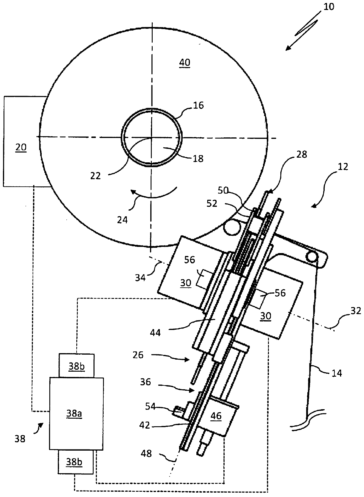
Figure 1 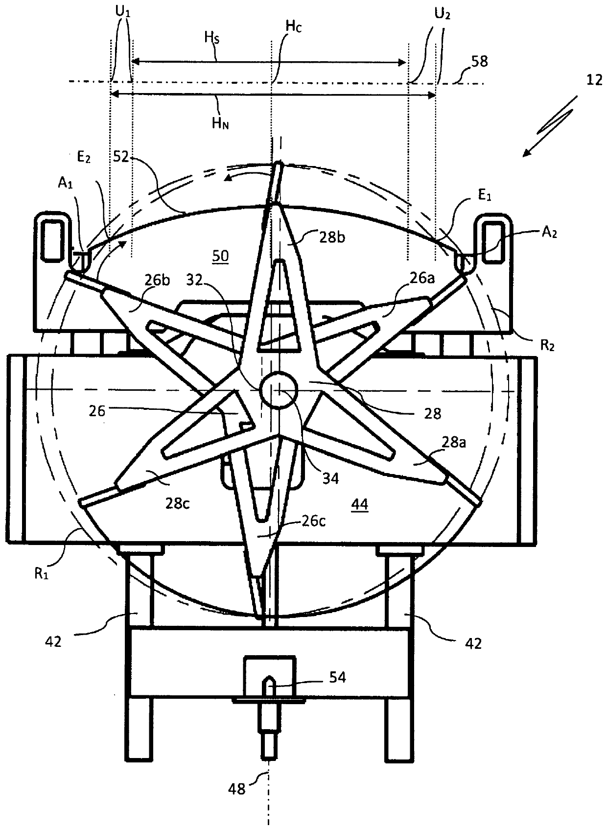
Figure 2 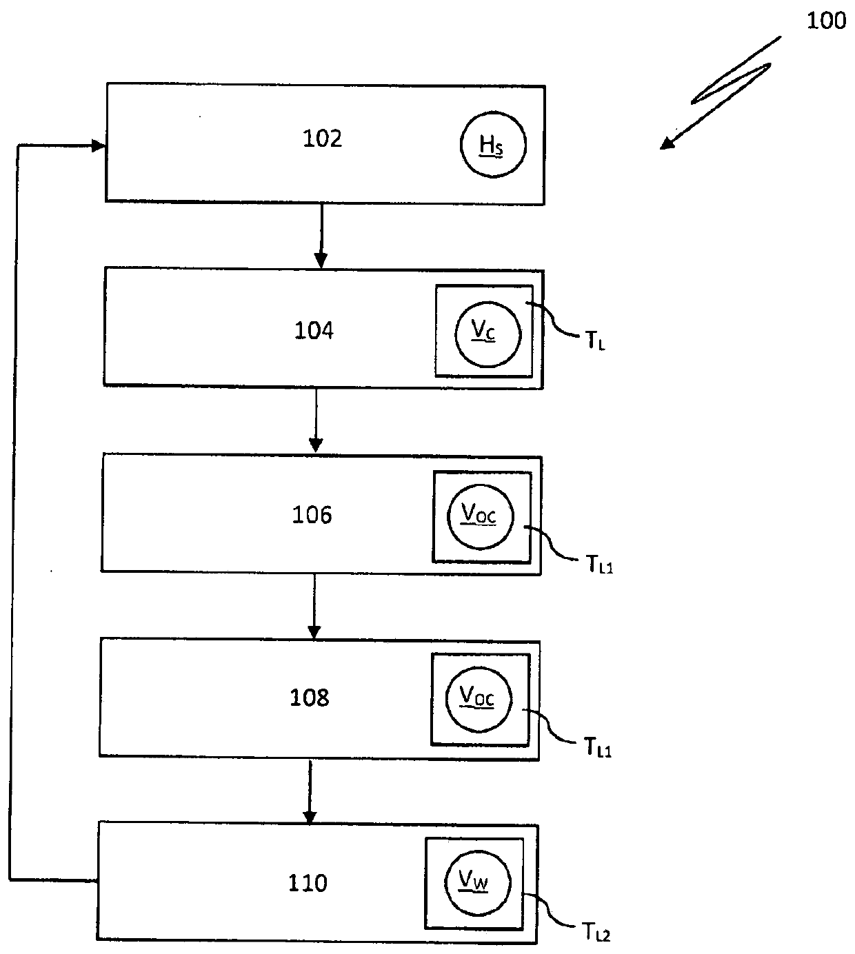
Figure 3
Abstract
Description
technical field
[0001] The invention relates to a method for controlling an impeller-type yarn laying device / yarn anti-lapping device, an impeller-type yarn laying device and a winder. Background technique
[0002] In the textile industry, yarn laying devices are used in the winding process, by which the yarn to be wound on a rotating bobbin is moved back and forth along the bobbin longitudinal axis by means of high-frequency reciprocating movements. Different designs of such thread laying devices have been established in practice. The thread laying device can be differentiated functionally into a thread laying device with a variable stroke distance and a thread laying device with a fixed stroke distance.
[0003] Yarn laying devices with variable travel distances allow a very free selection of winding configurations when winding yarn bobbins, such as bobbin edge bevelling, edge rounding or freedom to place the end winding in the desired longitudinal position of the bobbin ...
Examples
Embodiment Construction
[0050] figure 1 The winding position of a winder 10 with a yarn laying device 12 for winding a yarn 14 onto a bobbin 16 is shown. can be for example in figure 1 The yarn 14 to be wound on a bobbin 16 is provided on a storage bobbin not shown in detail. The bobbin 16 is arranged on a bobbin holder 18 and can be driven in rotation about its longitudinal axis 22 in the direction of the arrow 24 by a bobbin drive 20 .
[0051] The thread laying device 12 is designed as a so-called paddle wheel yarn laying device and has two paddle wheels 26 , 28 each. Independently of each other, the two impellers 26 , 28 can be driven in opposite directions about their respective axes of rotation 32 , 34 by means of an electric motor 30 . The electric motor 30 and the impellers 26 , 28 are arranged on a support frame 36 . A control device 38 serves to control the electric motor 30 of the two impellers 26 , 28 and the electric motor 20 of the bobbin holder 18 . The control device 38 has a sig...