
Electronic steering column lock and manufacturing process of shell of electronic steering column lock
A steering tube and housing technology is applied in the field of the production process of an electronic steering column lock and its housing. The effect of low tolerance requirements
Patent Information
- Authority / Receiving Office
- CN · China
- Current Assignee / Owner
- Publication Date
- 2018-04-20
Smart Images
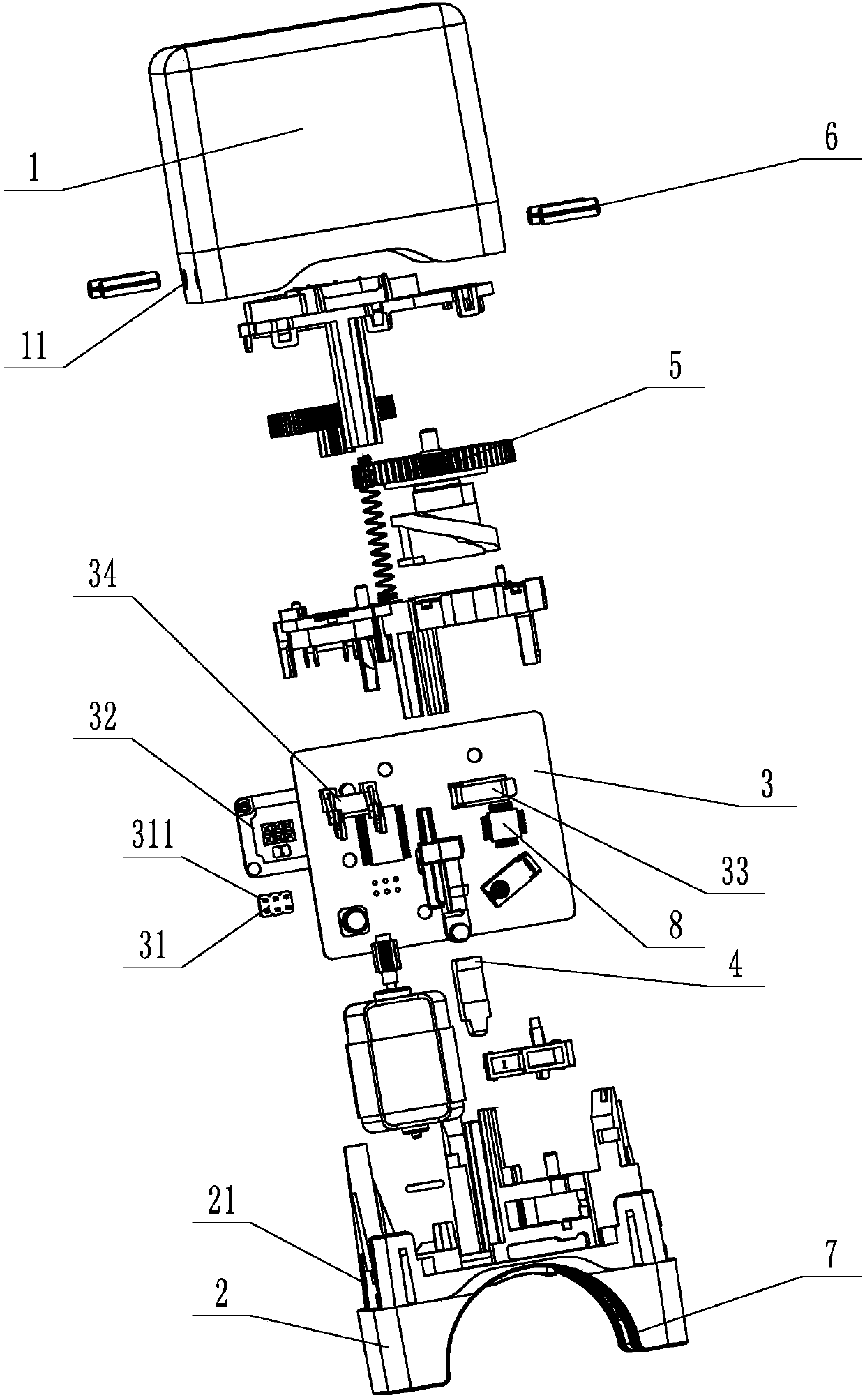
Figure 1 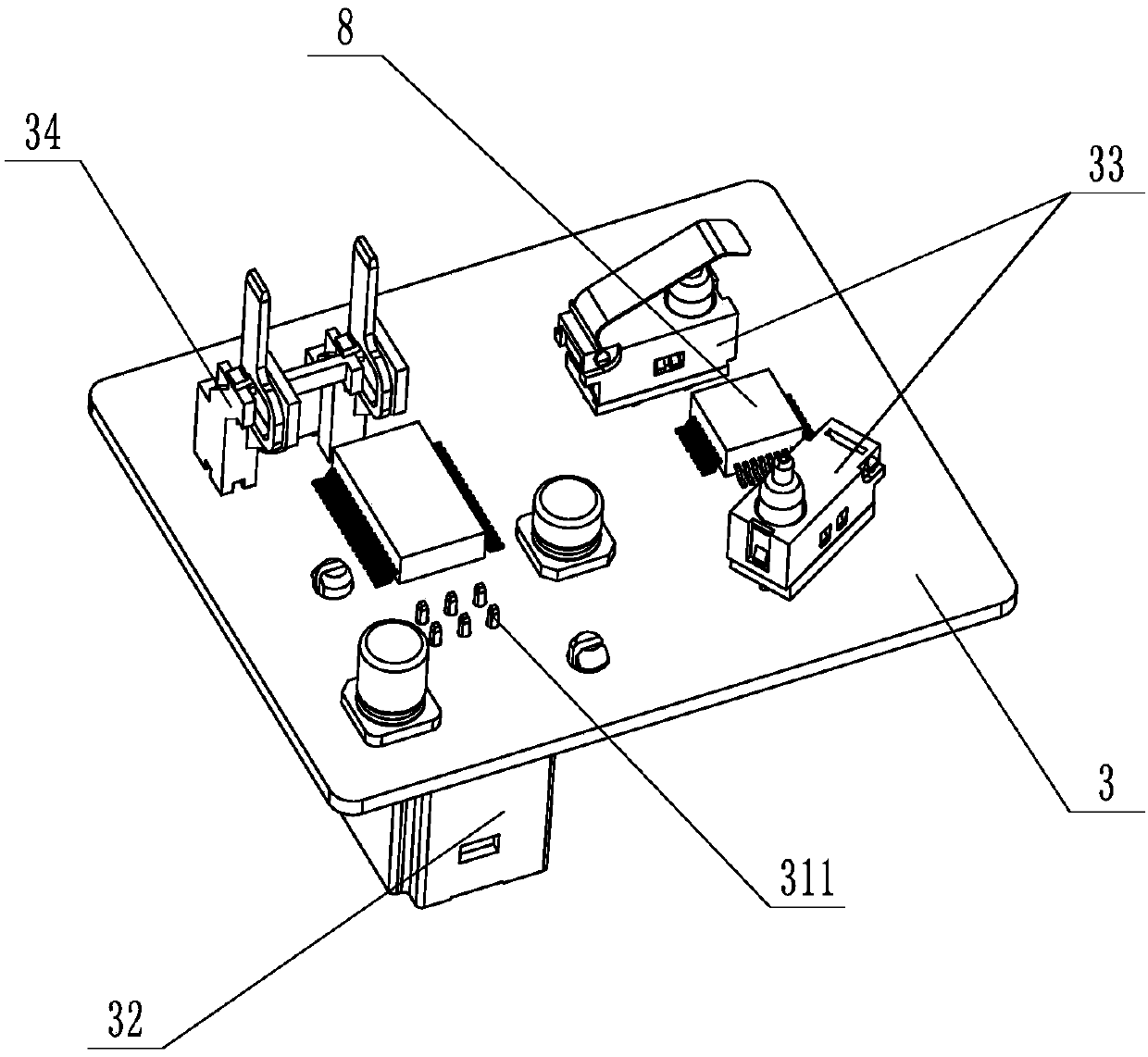
Figure 2 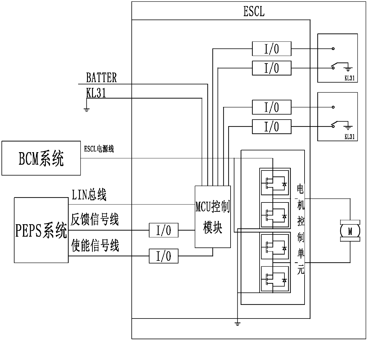
Figure 3
Abstract
Description
technical field
[0001] The invention relates to a manufacturing process of an electronic steering column lock and its shell. Background technique
[0002] The electronic steering column lock is a new product that replaces the traditional mechanical steering column lock, and it is mainly used with the smart key system or the keyless start system. In the parking state, the locking device will automatically lock the steering column to ensure that the steering wheel will not turn; and the steering wheel will be unlocked before the engine is started, and it needs to be kept unlocked during the entire driving process. The existing locking device comprises a dead bolt, a dead bolt spring, a dead bolt connecting rod and a safety bolt.
[0003] The shell and base of the existing electronic steering column lock are connected by anti-theft bolts to play an anti-theft effect, but this connection method can be easily opened as long as a suitable tool is used, so it is not safe. [0004...
Examples
Embodiment Construction
[0019] The specific implementation manners of the present invention will be further described in detail below in conjunction with the accompanying drawings and embodiments. The following examples are used to illustrate the present invention, but are not intended to limit the scope of the present invention.
[0020] Such as Figure 1 to Figure 3 An electronic steering column lock shown includes a housing 1, a base 2 matched with the housing 1, a circuit board 3 arranged in the housing 1, a control system 8, connecting elements, a locking device 4 and a driving The locking device 4 is used to lock the driving device 5, the two opposite side walls of the housing 1 are provided with through holes 11, and the base 2 is provided with a counterbore 21 at a position corresponding to the through holes 11. The through hole 11 is connected to the counterbore 21 through the elastic pin 6, and the housing 1 and the base 2 are connected by riveting through the elastic pin 6. The connecting...