
Passive low-pass filter
A low-pass filter and capacitor technology, applied in impedance network, electrical components, multi-terminal pair network, etc., can solve the problems of signal energy loss, large filter volume and weight, obvious load effect, etc., to reduce energy consumption and Attenuation effect
Patent Information
- Authority / Receiving Office
- CN · China
- Patent Type
- Applications(China)
- Current Assignee / Owner
- Publication Date
- 2018-06-19
- Estimated Expiration
- Not applicable · inactive patent
Smart Images
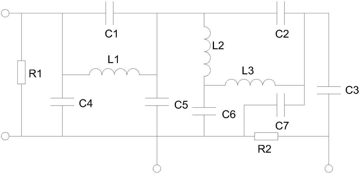
Figure 1
Abstract
Description
technical field
[0001] The invention relates to a filter circuit, in particular to a passive low-pass filter. Background technique
[0002] The power filter is a filter circuit composed of capacitors, inductors and resistors. The filter can effectively filter the frequency point of a specific frequency in the power line or frequencies other than this frequency point to obtain a power signal of a specific frequency or eliminate a power signal of a specific frequency. Among them, the passive filter is a filter composed of only passive components, which is composed of the principle that the reactance of capacitors and inductance components changes with frequency. The advantages of this type of filter are: the circuit is relatively simple, does not require DC power supply, and has high reliability; the disadvantage is: the signal in the passband has energy loss, the load effect is relatively obvious, and it is easy to cause electromagnetic induction when using inductive compone...
Examples
Embodiment Construction
[0016] The present invention will be further described below in conjunction with accompanying drawing:
[0017] This technology is mainly to protect the circuit structure, and the specific models of each electronic component and the parameters of resistance, capacitance, etc. are specified in detail. Those skilled in the art can pass the figure 1 The circuit diagram shown connects each electronic component, so as to achieve the purpose of this technology, that is, to solve the energy loss of the signal in the passband, and the load effect is relatively obvious. When using an inductive component, it is easy to cause electromagnetic induction. When the inductance L is large When the volume and weight of the filter are relatively large; and this is a circuit structure, as long as the various electronic components are connected through wires to form a complete circuit, its function can be realized, so no additional specific product structure is required.
[0018] Such as figure 1...