
High-frequency reciprocating motion mechanism
A reciprocating mechanism, high-frequency technology, applied in the direction of electromechanical devices, electric components, control mechanical energy, etc., can solve the problem of reducing the life of the eccentric wheel, and achieve the effect of avoiding material fatigue, simple structure and long service life
Patent Information
- Authority / Receiving Office
- CN · China
- Patent Type
- Applications(China)
- Current Assignee / Owner
- Publication Date
- 2018-07-10
- Estimated Expiration
- Not applicable · inactive patent
Smart Images
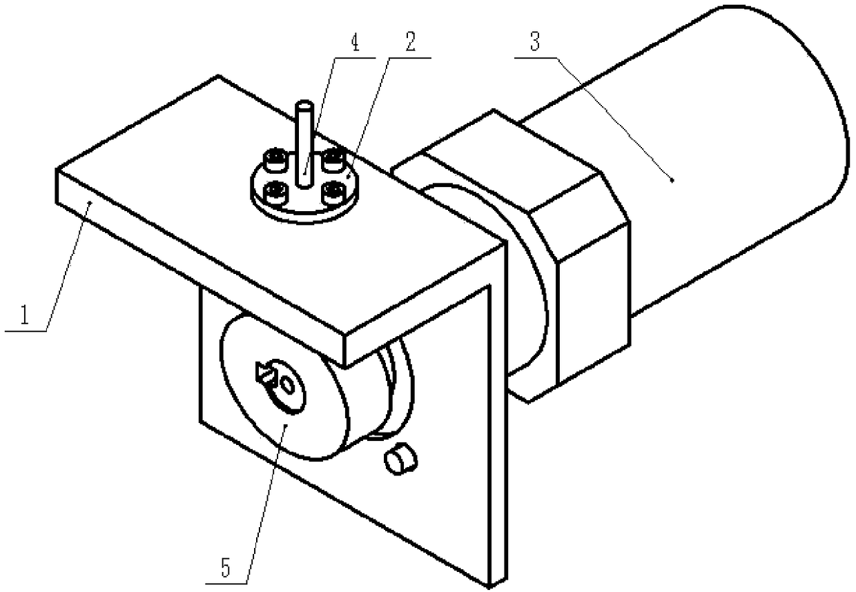
Figure 1 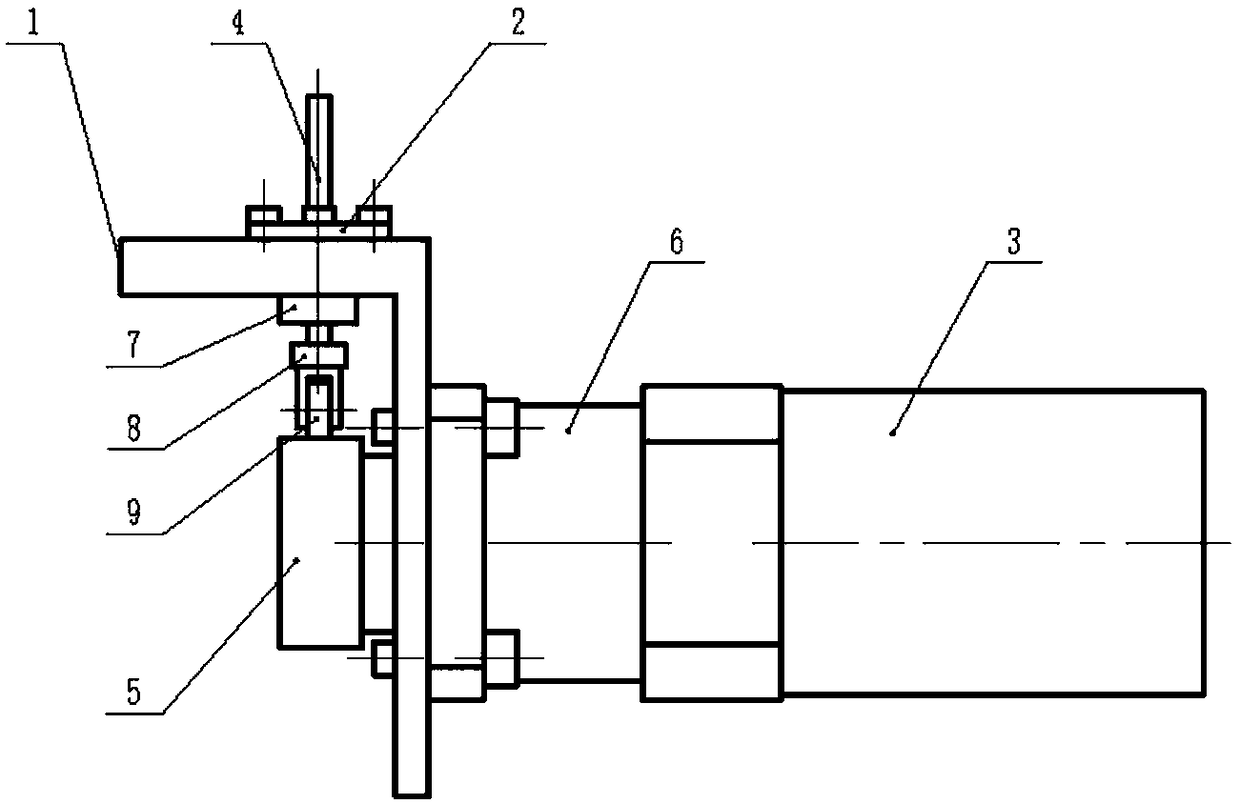
Figure 2 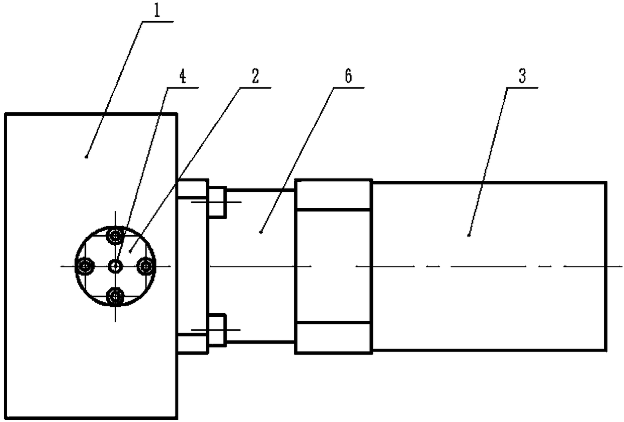
Figure 3
Abstract
Description
technical field
[0001] The invention belongs to the technical field of mechanical transmission, and in particular relates to a high-frequency reciprocating motion mechanism for converting circular motion into linear reciprocating motion. Background technique
[0002] In mechanical motion, reciprocating motion is a very common motion, which is generally realized by a crank slider mechanism. However, this method requires a huge torque to create a large reciprocating thrust. This kind of transmission mechanism often requires extremely high manufacturing costs, and the final transmission efficiency is not high, and there is an inertial impact at the dead point, and Since the slider crank mechanism generates high-frequency resistance during high-frequency reciprocating motion, the equipment will vibrate violently. In order to solve this problem, some use eccentric wheels. For example, on computerized cutting machines, eccentric wheels are used to realize the high-frequency recip...
Examples
Embodiment Construction
[0017] The present invention will be further described below in conjunction with the accompanying drawings and embodiments.
[0018] Such as Figure 1-5 As shown, the present invention provides a high-frequency reciprocating mechanism, including a connecting plate 1, a sleeve 2, a motor 3, a reciprocating shaft 4, an elliptical wheel 5, a reducer 6, a static magnet 7, a moving magnet 8, and a deep groove ball bearing 9. The connecting plate 1 is L-shaped, and the reducer 6 is installed on one side plate of the connecting plate 1, the output shaft of the reducer 6 passes through the side plate, and the elliptical wheel 5 is installed on the rotating shaft of the motor 3, and the motor 3 The output shaft is connected to the reducer 6, the sleeve 2 is installed on the other side of the connecting plate 1, the reciprocating shaft 4 slides through the sleeve 2, and the deep groove ball bearing 9 is supported on the lower end of the reciprocating shaft 4. The outer ring of groove b...