
Electromagnetic type jigging machine
A jigger and electromagnetic technology, which is applied in solid separation, wet separation, chemical instruments and methods, etc., can solve the problems of field workers' auditory system damage, jig vibration, short service life, etc., and achieve noise reduction. Small, small vibration, and the effect of reducing the damage of the auditory system
Patent Information
- Authority / Receiving Office
- CN · China
- Patent Type
- Applications(China)
- Current Assignee / Owner
- Publication Date
- 2018-08-10
- Estimated Expiration
- Not applicable · inactive patent
Smart Images
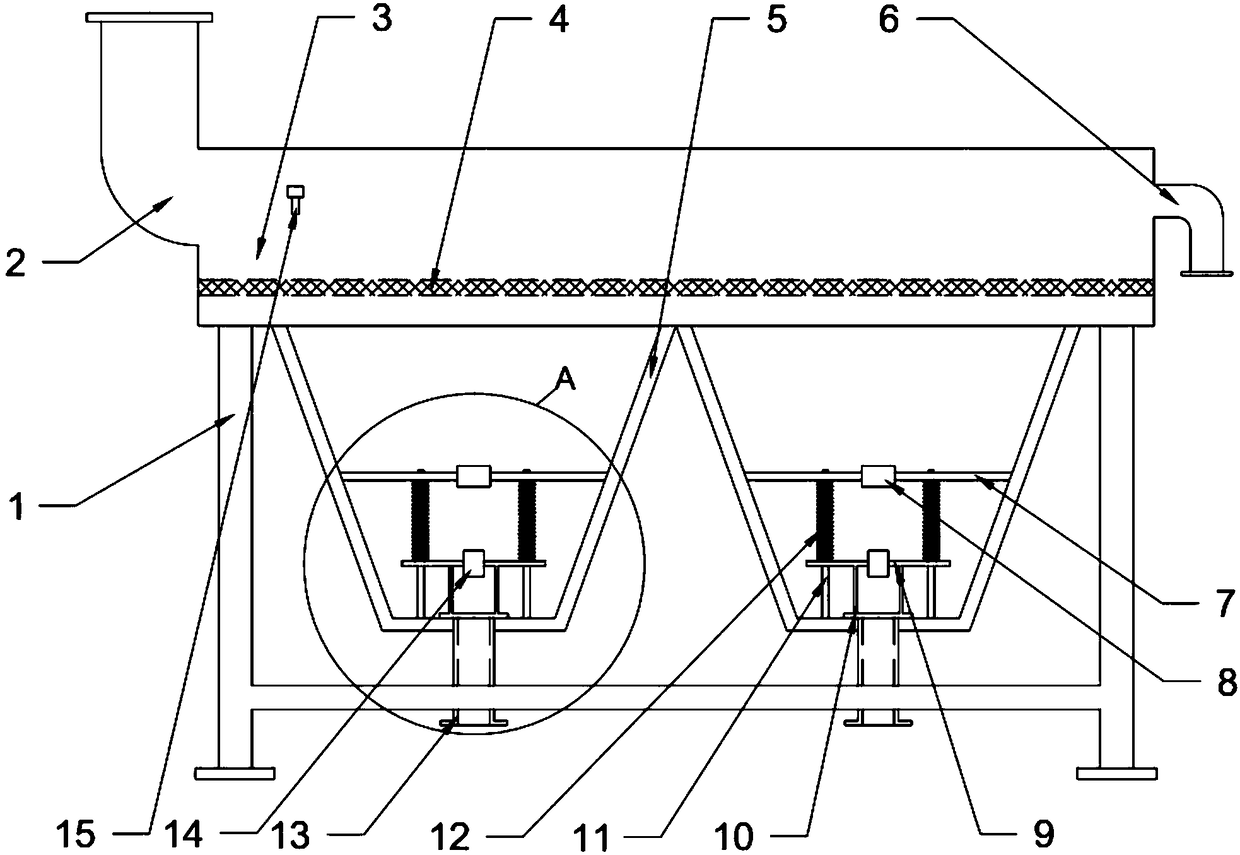
Figure 1 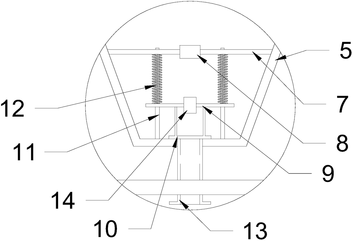
Figure 2
Abstract
Description
technical field
[0001] The invention relates to the field of coal mine equipment, in particular to an electromagnetic jig. Background technique
[0002] After coal is mined, it will generally go through a washing process. Coal washing generally refers to the process of removing gangue or other impurities from coal. The physical properties of coal and rock are used to make coal and gangue ( impurities) are separated. Coal washing can improve coal quality, reduce coal-burning pollutant emissions, improve coal utilization efficiency, save energy, optimize product structure, improve product competitiveness, and reduce transportation cost.
[0003] At present, jigging is the most mainstream coal washing method. The materials are mainly sorted according to the density difference in the vertically ascending and variable medium flow, and the minerals can be re-stratified under the action of the vertical alternating medium flow. The mineral particles with higher density settle quic...
Examples
Embodiment 1
[0028] see figure 1 , an electromagnetic jig, comprising a frame 1, a slot 3 is installed above the frame 1, a feeding pipe 2 is installed at one end of the slot 3, and a discharge port 6 is installed at the other end, the bottom of the slot 3 is connected to the two A cone bucket 5 is connected, and a bracket 7 is installed inside the cone bucket 5, an electromagnet 8 is installed on the bracket 7, a slide bar 11 is connected with the bottom of the cone bucket 5 downward on the bracket 7, and a shock plate 9 is arranged below the bracket 7, and the shock plate 9 is provided with a positioning hole through which the slide bar 11 passes, and the inner wall surface of the positioning hole is attached to the outer wall surface of the slide bar 11 , and a magnet 14 is installed on the shock plate 9 .
[0029] In this example, the raw coal is crushed and sieved and mixed with water, and flows into the passage 3 on the frame 1 through the feed pipe 2, and the electromagnet 8 in the ...
Embodiment 2
[0031] see figure 1 , an electromagnetic jig, comprising a frame 1, a slot 3 is installed above the frame 1, a feeding pipe 2 is installed at one end of the slot 3, and a discharge port 6 is installed at the other end, the bottom of the slot 3 is connected to the two A cone bucket 5 is connected, and a bracket 7 is installed inside the cone bucket 5, an electromagnet 8 is installed on the bracket 7, a slide bar 11 is connected with the bottom of the cone bucket 5 downward on the bracket 7, and a shock plate 9 is arranged below the bracket 7, and the shock plate 9 is provided with a positioning hole through which the slide bar 11 passes, and the inner wall surface of the positioning hole is attached to the outer wall surface of the slide bar 11 , and a magnet 14 is installed on the shock plate 9 .
[0032] There is a row of ore openings at the bottom of the cone bucket 5, and an ore discharge pipe 13 is connected to the bottom of the ore discharge opening. The denser mineral pa...
Embodiment 3
[0034] see figure 1 , an electromagnetic jig, comprising a frame 1, a slot 3 is installed above the frame 1, a feeding pipe 2 is installed at one end of the slot 3, and a discharge port 6 is installed at the other end, the bottom of the slot 3 is connected to the two A cone bucket 5 is connected, and a bracket 7 is installed inside the cone bucket 5, an electromagnet 8 is installed on the bracket 7, a slide bar 11 is connected with the bottom of the cone bucket 5 downward on the bracket 7, and a shock plate 9 is arranged below the bracket 7, and the shock plate 9 is provided with a positioning hole through which the slide bar 11 passes, and the inner wall surface of the positioning hole is attached to the outer wall surface of the slide bar 11 , and a magnet 14 is installed on the shock plate 9 .
[0035] Oscillating plate 9 is downwardly connected with ore discharge baffle 10, and ore discharge baffle 10 can block the ore discharge outlet, reduce the amount of replenishing wa...