
A Method of Attitude Positioning Error Correction Based on Mems Inertial Measurement Unit
An inertial measurement unit and positioning error technology, applied in the field of inertial navigation, can solve problems such as the inability to use external information sources, achieve the effect of improving attitude positioning accuracy and reducing movement attitude positioning errors
Patent Information
- Authority / Receiving Office
- CN · China
- Patent Type
- Patents(China)
- Current Assignee / Owner
- Publication Date
- 2021-06-08
Smart Images
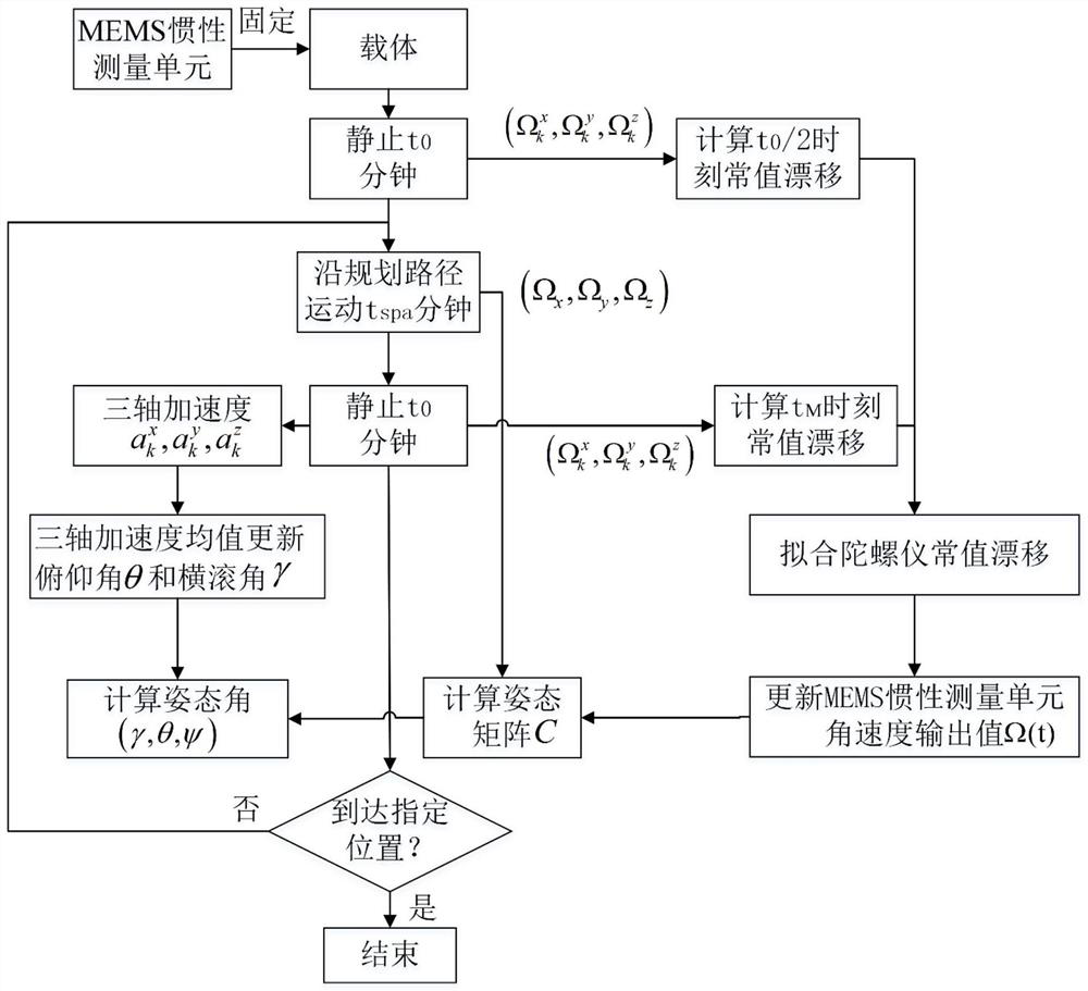
Figure 1 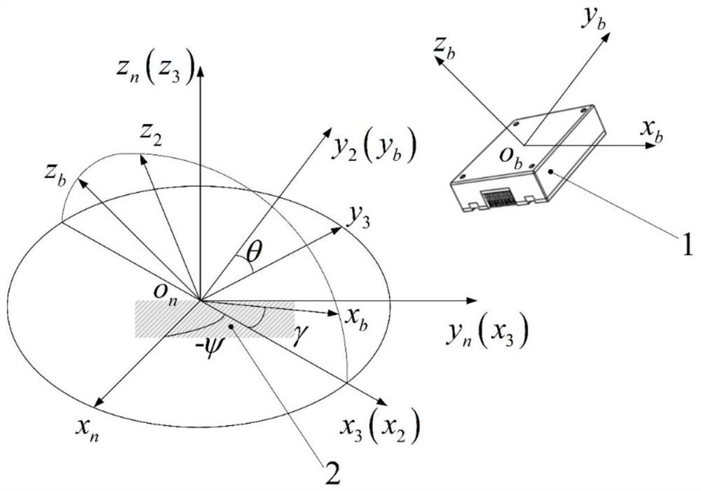
Figure 2 
Figure 3
Abstract
Description
technical field
[0001] The invention belongs to the technical field of inertial navigation, and in particular relates to a posture positioning method for robot curved surface movement, which is suitable for mobile robots using MEMS inertial measurement units to perform posture positioning in operating environments such as indoors and strong magnetic interference. Background technique
[0002] MEMS inertial measurement unit combines sensors such as gyroscopes, accelerometers and magnetometers in a multi-axis manner to provide navigation and attitude data in a dynamic environment, and is widely used in mobile robots, drones, spacecraft, etc. The field of measurement and control.
[0003] Inertial navigation is a common attitude measurement method. Attitude information can be calculated by integrating the three-axis motion angular velocity measured by the MEMS inertial measurement unit gyroscope. The MEMS inertial measurement unit gyroscope is composed of micro-mechanical com...
Examples
Embodiment Construction
[0043] The present invention will be described in more detail below in conjunction with the accompanying drawings and embodiments.
[0044] figure 1 A flow chart of a MEMS inertial measurement unit-based attitude positioning error correction method provided by the present invention is illustrated. The method includes the following steps:
[0045] 1) Define γ as the roll angle, θ as the pitch angle, and ψ as the heading angle, and establish a navigation coordinate system fixed on the ground at the initial position of the carrier motion o n -x n the y n z n ;Establish the IMU coordinate system o on the MEMS IMU b -x b the y b z b ; Set the navigation coordinate system o n -x n the y n z n z around itself n Rotate the axis by -ψ angle to get the coordinate system o-x 3 the y 3 z 3 , set the coordinate system o-x 3 the y 3 z 3 around itself x 3 Rotate the axis by θ angle to get the coordinate system o-x 2 the y 2 z 2 , set the coordinate system o-x 2 the y ...