
Clamping device applied to trimming arc surfaces of abrasive blocks of grinding wheel
An abrasive block and arc surface technology, which is used in abrasive surface adjustment devices, parts of grinding machine tools, grinding/polishing equipment, etc., can solve the problem of abrasive blocks flying away from the base of the grinding wheel, inconsistency in shape and size, and poor workpiece quality. and other problems, to achieve the effect of convenient and quick fixation, high consistency and good economy.
Patent Information
- Authority / Receiving Office
- CN · China
- Current Assignee / Owner
- Publication Date
- 2018-10-23
Smart Images
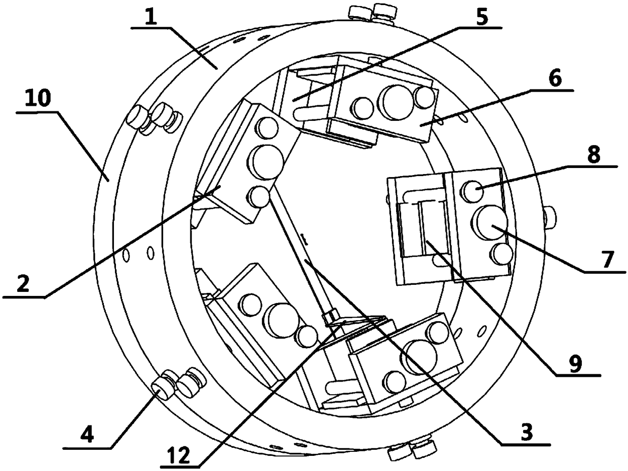
Figure 1 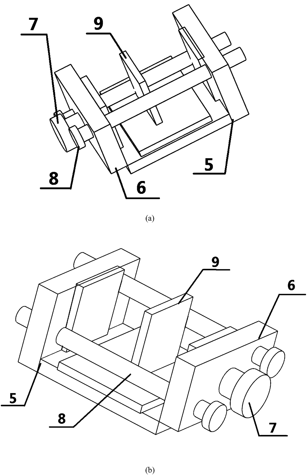
Figure 2 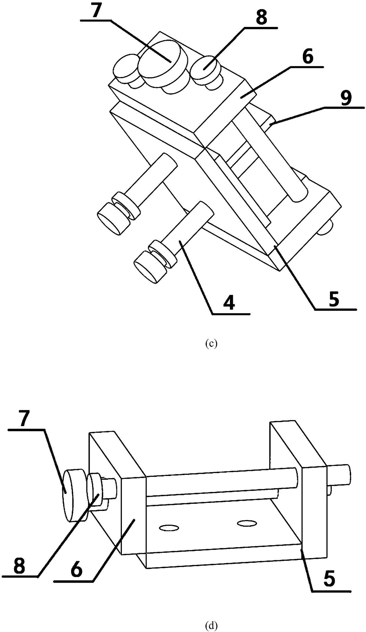
Figure 3
Abstract
Description
technical field
[0001] The invention relates to the technical field of vitrified bond grinding wheel manufacturing and processing, in particular to a clamping device for dressing the arc surface of an abrasive block of a grinding wheel. Background technique
[0002] In order to process and produce high-quality, high-durability ceramic grinding wheels, many companies paste the sintered grinding wheel abrasive blocks on the grinding wheel substrate, but the pressed abrasive blocks will undergo certain deformation after high-temperature sintering, resulting in During the bonding process of the substrate, the shape and size do not match, which will cause the abrasive block to fly away from the grinding wheel substrate during the high-speed rotation of the grinding wheel, causing danger, and will also lead to poor quality of the ground workpiece. Contents of the invention
[0003] The invention provides a clamping device for dressing the arc surface of the abrasive block of the...
Examples
Embodiment Construction
[0022] In conjunction with the accompanying drawings of the description, this invention is carefully interpreted:
[0023] Such as figure 1 , Figure 5 As shown in (a) to (c), a clamping device applied to trim the arc surface of grinding wheel abrasive blocks, including: a circular outer casing 1, a clamp body 2 for clamping arc-shaped abrasive blocks; several clamps Concrete 2 is evenly distributed and connected on the jacket 1 with the center of the jacket 1 as the center.
[0024] Such as figure 2 The clamp body 2 shown in (a) to (d) includes: clamping front pressure plate 6, L-shaped clamping rear bottom plate 5, connecting screw 8 and clamping screw 7, clamping front pressure plate 6 and clamping rear bottom plate 5 is connected and fixed by the connecting screw 8, and the arc-shaped abrasive block 11 is clamped between the clamping front pressure plate 6 and the clamping rear bottom plate 5; The clamping force is adjusted by clamping screw 7, such as figure 2 (a) ...