
MovabLe guide device for steeL strand threading and use method thereof
A technology of guiding device and steel strand, which is applied in the direction of construction, building structure, and building material processing, etc. It can solve problems such as failure to meet beam penetration requirements, difficult operation, and economic loss in construction, and achieve construction quality and safety. Easy to control, improve traction efficiency and save construction cost
Patent Information
- Authority / Receiving Office
- CN · China
- Patent Type
- Applications(China)
- Current Assignee / Owner
- Publication Date
- 2018-11-23
Smart Images
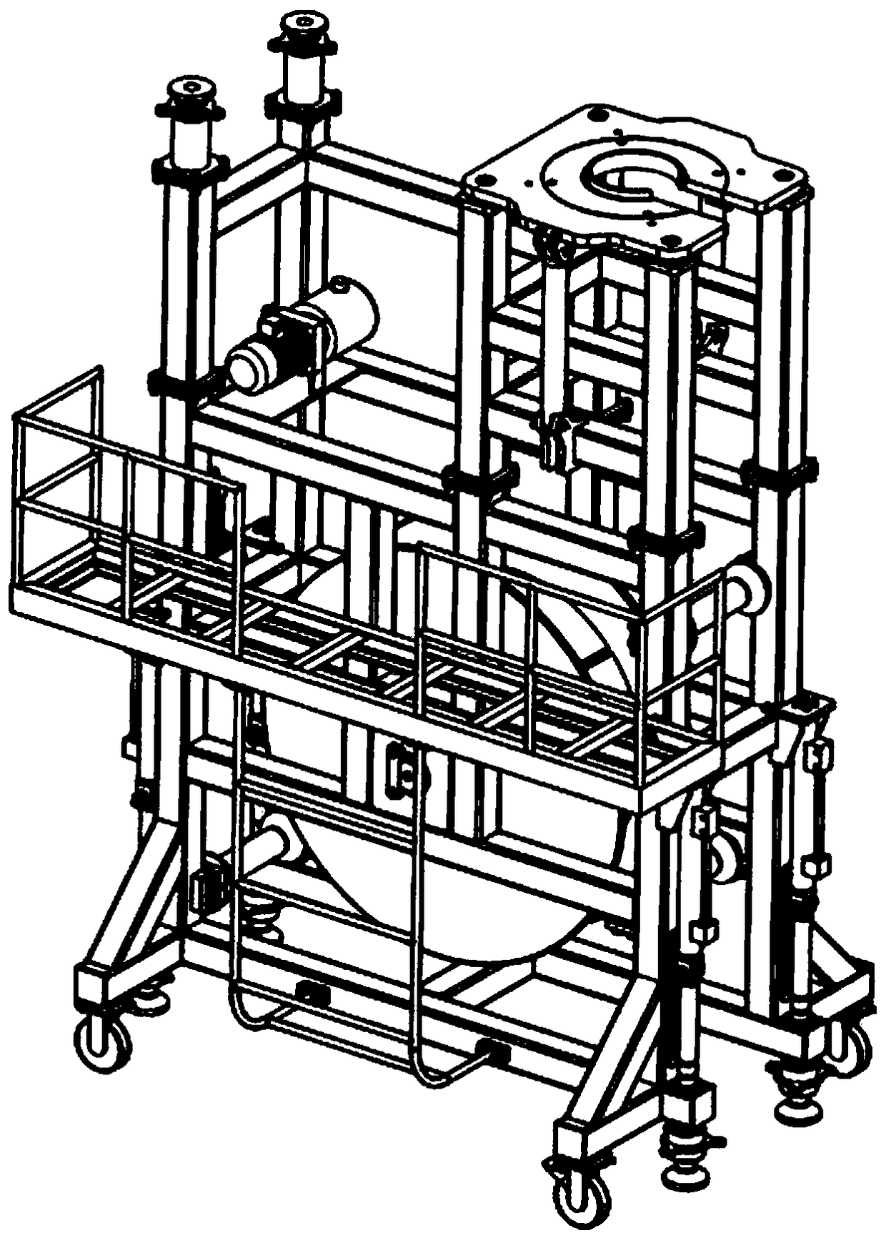
Figure 1 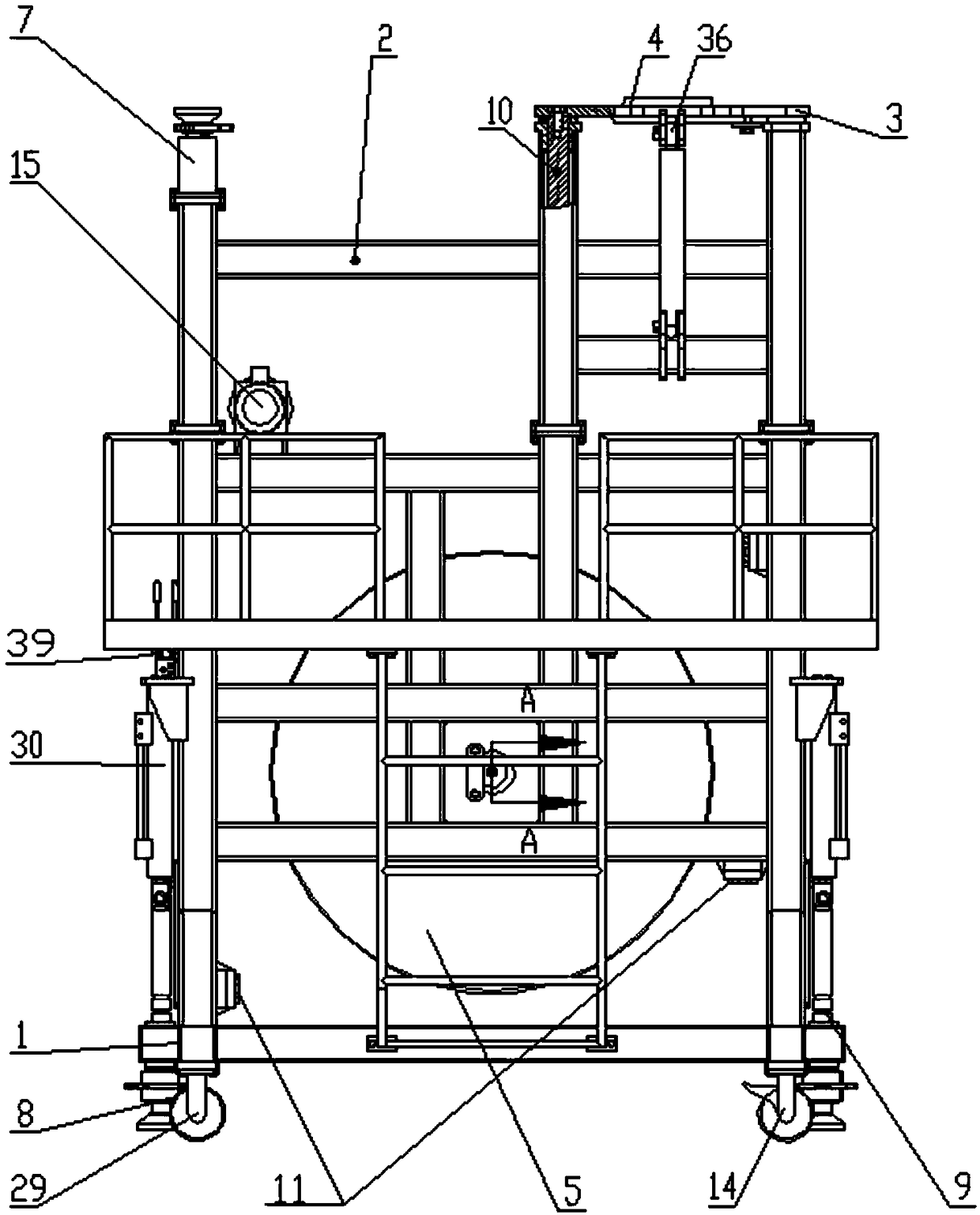
Figure 2 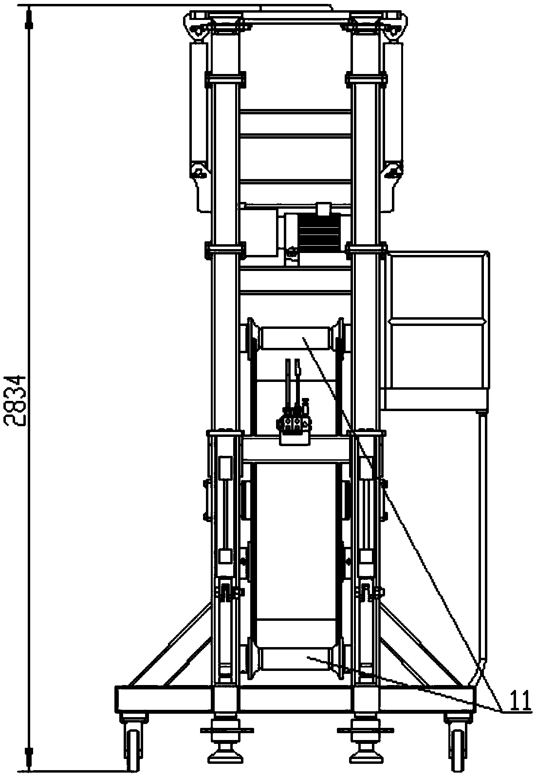
Figure 3
Abstract
Description
technical field
[0001] The invention relates to the technical field of building construction, in particular to a movable beam-threading guide device for steel strands and an application method thereof. Background technique
[0002] With the vigorous development of my country's third-generation nuclear power and the wide application of prestressing technology, when the vertical inverted U-shaped prestressed beam of the containment prestressed system of Hualong No. 1 is constructed through the beam, the prestressed steel conduit has a large curvature and a long length , the tonnage of the steel strand bundle is large. When the existing ordinary steel strand threading method is used, the threading resistance is too large and the steel strand is too long to meet the threading requirements. A large hoist must be used for the overall threading. However, due to the space When the hoist is directly pulled at the bottom of the steel pipe, the space is narrow, the installation is inconv...
Examples
Embodiment Construction
[0022] The present invention will be further described below in conjunction with specific examples.
[0023] A movable steel strand threading guide device, including a frame, a guide roller 5, a top tightening device and a frame lifting device; the frame is composed of a lower frame 1, an upper frame 2 and a lifting device 3, and the guide roller 5 is located in the formed frame, the lifting device 3 includes a threaded jack 7, a threaded sleeve 8, a push rod 9 and a lifting device cylinder 30, and the tightening device includes a butt plate 4 and a tightening jack cylinder, the Lifting device 3 , guide rod 10 , butt plate 4 are docked with the pressure bearing plate of the steel pipe bundle; the frame lifting device includes an operating valve 39 and a hydraulic pump station 15 for controlling the lifting of the frame.
[0024] The front universal caster 14 and the rear directional caster 29 are provided below the frame to control the front and rear movement.
[0025] The ja...