
Laser calligraphy mesh division ruler and control system thereof
A technique of calligraphy and division, applied in writing utensils, printing, etc., to achieve the effect of precise adjustment
Patent Information
- Authority / Receiving Office
- CN · China
- Current Assignee / Owner
- Publication Date
- 2018-11-30
- Estimated Expiration
- Not applicable · inactive patent
Smart Images
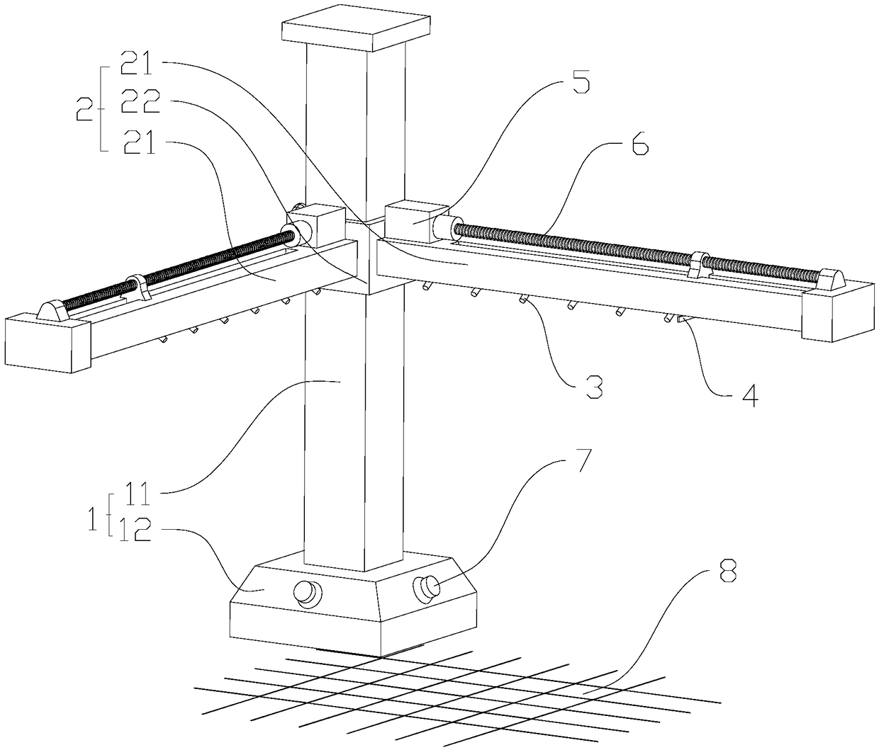
Figure 1 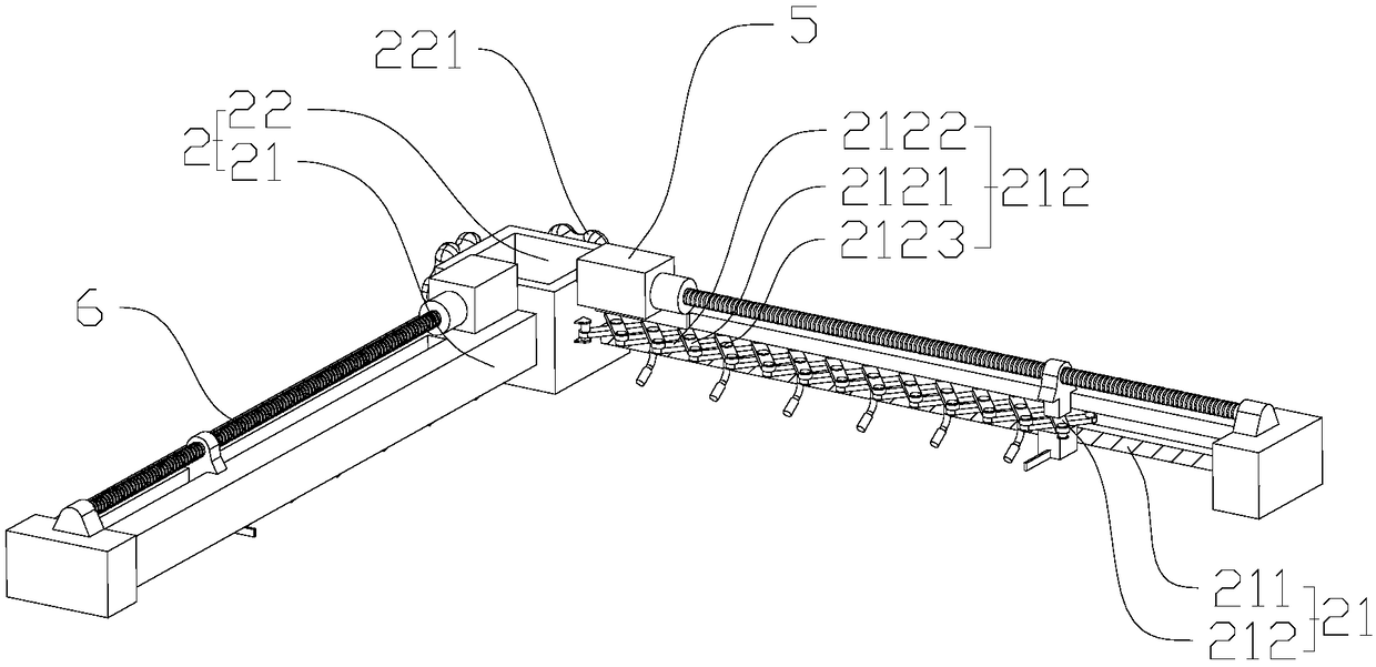
Figure 2 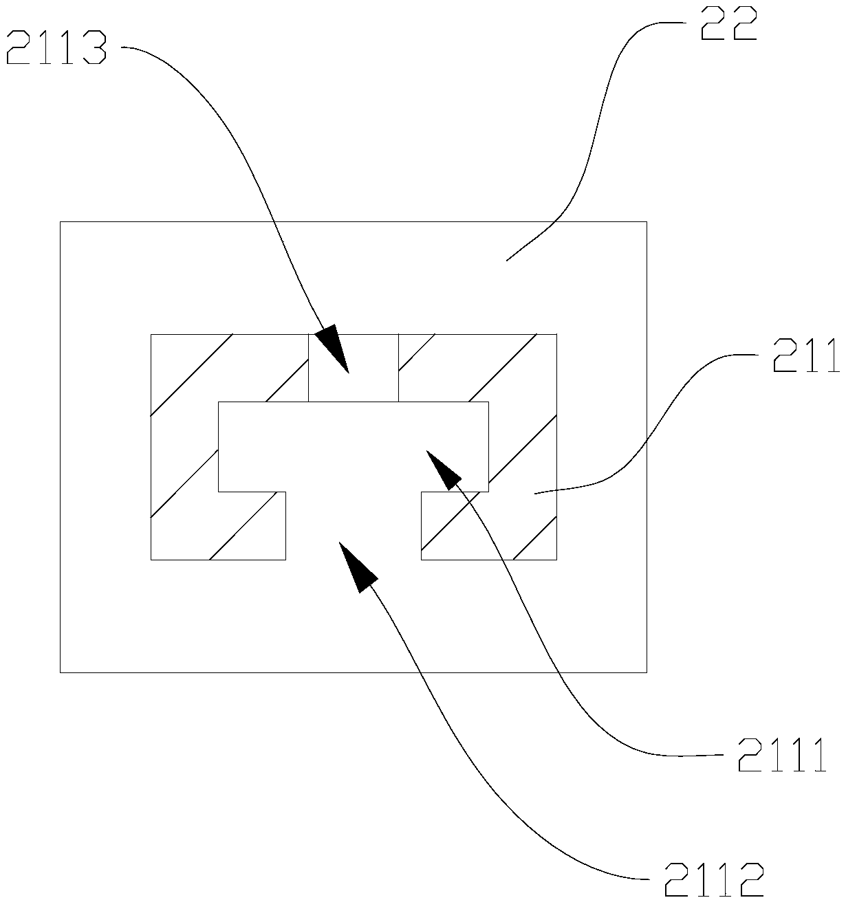
Figure 3
Abstract
Description
technical field
[0001] The invention relates to a writing aid, in particular to a laser calligraphy ruler and a control system thereof. Background technique
[0002] The traditional calligraphy division method, after repeated calculations, needs to manually fold, draw, overlap or penetrating writing. It is required to make the division clear and accurate. Wait. Therefore, calligraphers have always been troubled by "three-point grid, seven-point writing"; at the same time, the crumpled rice paper caused by folding grids, grids, and stacking grids cannot carry out calligraphy creation smoothly, and there are improvements in the existing technology . Contents of the invention
[0003] In order to solve the above-mentioned technical problems, the present invention proposes a laser calligraphy dividing grid, which forms the grating of the book on the paper surface through the laser emitters arranged at intervals on the horizontal support rod, so as to avoid the folding of the...
Examples
Embodiment 1
[0030] like figure 1 Shown, a kind of laser calligraphy divides grid ruler, comprises vertical support 1, and vertical support 1 comprises vertical support rod 11, and the two ends of vertical support rod 11 are respectively provided with supporting base 12 and horizontal support 2, horizontal The support 2 includes two horizontal support bars 21 perpendicular to each other. The horizontal support bars 21 are provided with a number of laser emitters 3 distributed at intervals. The laser emitters 3 on the vertical and horizontal support rods 21 form a light grid 8 on the paper. combine figure 2 As shown, the horizontal support rod 21 includes a rod body 211 and a scissor movable frame 212 arranged in the rod body 211. The scissor movable frame 212 extends along the length direction of the rod body 211 and one end of the scissor movable frame 212 is connected to the rod. The main body 211 is hinged, and the laser emitters 3 are arranged on the scissor movable frame 212 at equ...
Embodiment 2
[0034] An automatic control system for optical calligraphy rulers, including controllers, actuators and transmission components, such as figure 1 and 2 As shown, the transmission assembly includes a transmission screw 6 arranged along the length direction of the rod body 211, the transmission screw 6 penetrates the adjustment caliper 4 and is threadedly connected with the adjustment caliper 4; the actuator is a servo motor 5 that drives the transmission screw 6 to rotate ; combine Figure 4As shown, the controller includes a knob 7 arranged on the support base 12 and a control module 9 for controlling the rotation of the servo motor 5. The knob 7 is provided with two correspondingly controlled horizontal support rods 21 that are perpendicular to each other. In this program, the knob 7 is connected to There is an angle sensor 71, which converts the amount of rotation and the direction of rotation of the knob 7 into electrical signals. The control module 9 includes a processing...