
Single-diversion-tunnel water-power engineering hoist arrangement structure
A technology for water diversion tunnels and hydropower projects, which is applied in water conservancy projects, hydroelectric power generation, hydropower stations, etc. It can solve the problems of increasing investment, increasing the amount of excavation and concrete pouring, and achieves the effect of saving investment
Patent Information
- Authority / Receiving Office
- CN · China
- Current Assignee / Owner
- Publication Date
- 2019-02-19
Smart Images
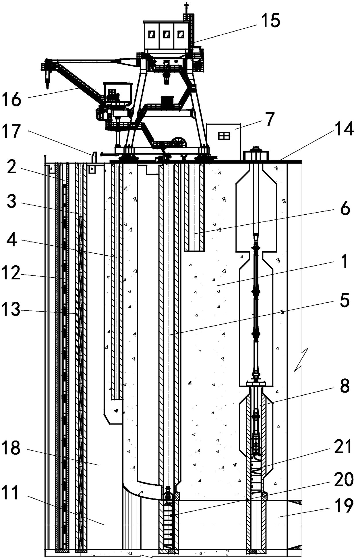
Figure 1 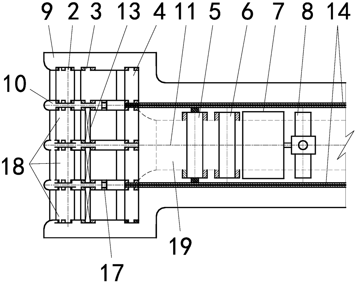
Figure 2 
Figure 3
Abstract
Description
technical field
[0001] The invention relates to an arrangement structure of a hoist for a hydropower project of a single diversion tunnel, and belongs to the technical field of metal structures of a water conservancy and hydropower project. Background technique
[0002] For hydropower projects, trash racks, layered water intake stack gates, maintenance gates and fast gates are usually arranged in sequence along the water inlet flow direction. Adopt two-way cleaning door machine operation, set one fast gate for each hole and use a single-cylinder vertical hydraulic hoist to operate, and set up a multi-hole shared inspection gate and use two-way door machine operation, consider storing stacked beams for layered water intake Gates and maintenance gates require layered water intake stacking gates and maintenance gates to be installed at the end of the vertical water flow of the water inlet. The existing technical scheme is reasonable for hydropower projects with more than two wa...
Examples
Embodiment
[0018] In this example, the trash rack slot 2, layered water intake stack beam door slot 3, layered water intake stack beam door storage 4, maintenance gate slot 5, maintenance gate storage 6, and hydraulic pump room 7 are sequentially arranged at the water inlet of the dam body 1 along the water flow direction And fast gate slot 8. The front section of the single diversion tunnel is divided into multiple flow channels 18 by two side piers 9 and more than one middle pier 10 ; the rear section of the single diversion tunnel is a single flow channel 19 .
[0019] Each flow channel of the multi-runner 18 is provided with a trash rack slot 2; a trash rack 12 is arranged in each trash rack slot 2; a layered water intake stack is arranged behind each trash rack slot 2 Beam door slot 3; each layered water intake stack door slot 3 is provided with a layered water intake stack door 13; each layered water intake stack door slot 3 is equipped with a layered water intake stack door storeh...