
Electro-hydraulic air-lock gate valve
A flapper valve and flapper technology, applied in the direction of sliding valves, valve details, valve devices, etc., can solve the problems of bulky electro-hydraulic air-locked flapper valves, high production costs, high labor costs, etc., and achieve a large market application prospect , Improve the sealing effect, the effect of good sealing
Patent Information
- Authority / Receiving Office
- CN · China
- Patent Type
- Applications(China)
- Current Assignee / Owner
- Publication Date
- 2019-03-26
- Estimated Expiration
- Not applicable · inactive patent
Smart Images
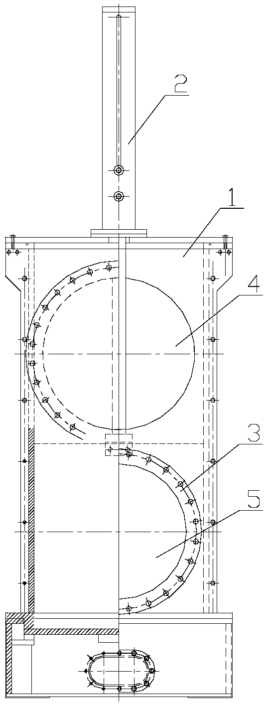
Figure 1 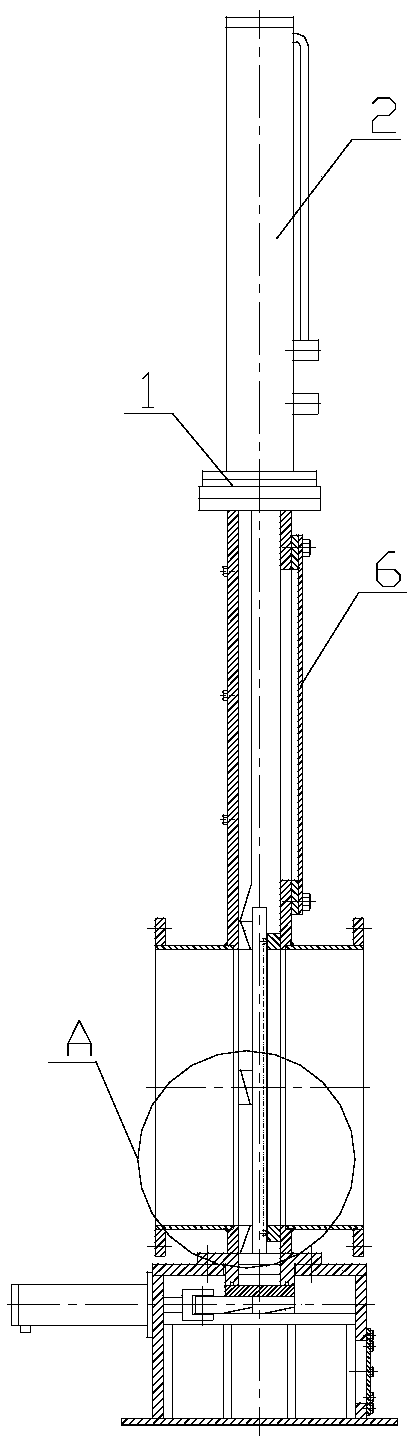
Figure 2 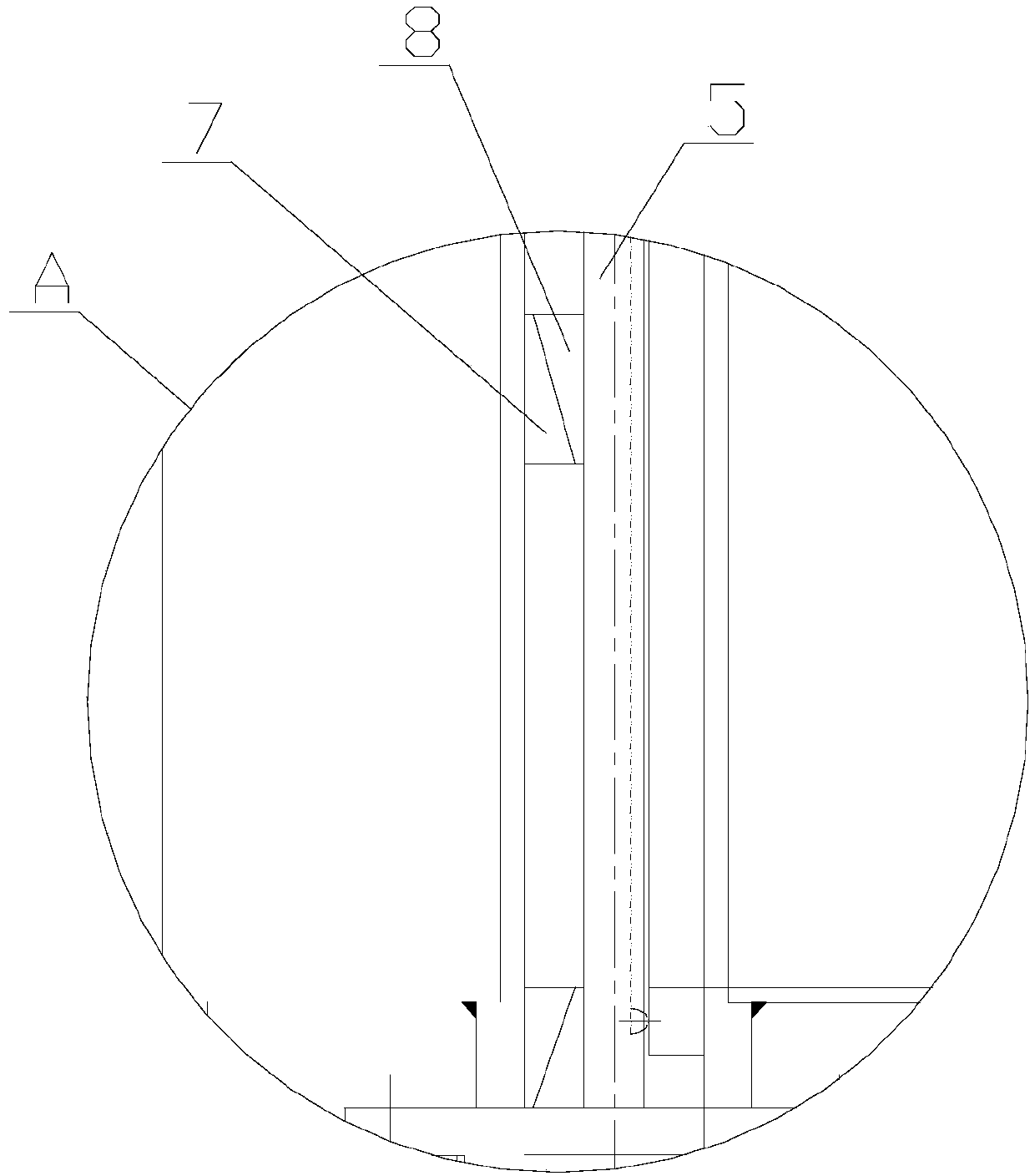
Figure 3
Abstract
Description
technical field
[0001] The invention relates to an electro-hydraulic air-locking plate valve. Background technique
[0002] The electro-hydraulic air-locking flapper valve is mainly used in gas pipeline transportation to open or close the transportation channel.
[0003] The existing electro-hydraulic air-locking flapper valve is relatively bulky and expensive to manufacture, and it is very troublesome to maintain the wearing part-the sealing ring. The whole shell needs to be disassembled to realize the replacement, the process is complicated, and the labor cost is also very high. High, and, the internal plug-in plate is generally driven by a transmission component, such as a gear combination, so as to achieve sealing. After a long time of use, it is not only inconvenient to clean the internal impurities, but also due to the wear and tear between the components, And cause the phenomenon of air leakage to take place, practicality is not strong. Contents of the invention ...
Examples
Embodiment Construction
[0021] The present invention is described in further detail now in conjunction with accompanying drawing. These drawings are all simplified schematic diagrams, which only illustrate the basic structure of the present invention in a schematic manner, so they only show the configurations related to the present invention.
[0022] Such as figure 1 with 2 As shown, an electro-hydraulic air-locking gate valve includes a main body 1, an oil cylinder 2 is arranged above the main body 1, a strip-shaped cavity is provided inside the main body 1, and a gate plate is provided in the cavity 5. The inserting plate 5 is connected to the piston rod of the oil cylinder 2, the two sides of the lower part of the main body 1 are provided with through holes 3, and one side of the upper part of the main body 1 is provided with a manhole 4, and the manhole 4 One of the through holes 3 is located on the same side of the main body 1, the inner diameter of the manhole 4 is larger than the inner diam...