
Electronic electrodeless noise reduction adjustment device
A technology of adjusting device and noise reduction, applied in the components of pumping device for elastic fluid, pump control, non-variable-capacity pump, etc., can solve problems such as waste of electric energy and inaccurate judgment of detection signal.
Patent Information
- Authority / Receiving Office
- CN · China
- Current Assignee / Owner
- Publication Date
- 2019-05-10
- Estimated Expiration
- Not applicable · inactive patent
Smart Images
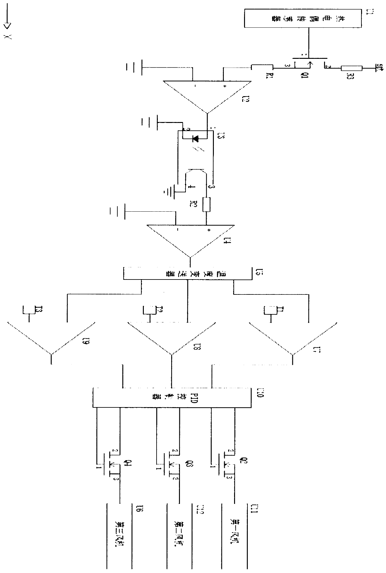
Figure 1
Abstract
Description
technical field
[0001] The invention relates to the technical field of adjustment devices, in particular to an electronic stepless noise reduction adjustment device. Background technique
[0002] The existing high-power resistors used to test the load capacity of generators, power supplies, UPS and other equipment are generally made in the form of forced air cooling by cooling fans in order to simplify design, reduce volume, and reduce costs. Conventional automatic load resistors will be equipped with axial flow fans to cool the load with forced air, and the noise reduction treatment on the automatic load resistor needs a special stepless noise reduction adjustment device to complete, the existing automatic load resistor When the stepless noise reduction adjustment device heats up the automatic load resistors, all the fans on the automatic load resistors will be turned on, resulting in a waste of electric energy, and the automatic load resistor stepless noise reduction adjus...
Examples
Embodiment Construction
[0014] The following will clearly and completely describe the technical solutions in the embodiments of the present invention with reference to the accompanying drawings in the embodiments of the present invention. Obviously, the described embodiments are only some, not all, embodiments of the present invention.
[0015] Such as figure 1 As shown, an electronic stepless noise reduction adjustment device includes a shell body and a resistor, the input end of the resistor is connected to the output end of the element U4, and the negative input end of the element U4 is grounded, and the positive input end of the element U4 The resistor R2 is connected, and the other end of the resistor R2 is connected to the pin 3 of the coupler U3, the pin 2 and the pin 4 of the coupler U3 are both grounded, and the pin 1 of the coupler U3 is connected to the pin of the element U2 output terminal, the negative output terminal of the component U2 is grounded, and the positive input terminal of th...