
A self-excited pump driven by two oscillators
A dual vibrator and vibrator technology, applied to pumps with flexible working elements, pumps, machines/engines, etc., can solve the problem of low output flow and pressure accuracy, poor flatness and cut-off effect, pump output flow and pressure drop, etc. problem, to achieve the effect of improving output capability and control accuracy, good cut-off effect, and high output efficiency
Patent Information
- Authority / Receiving Office
- CN · China
- Patent Type
- Patents(China)
- Current Assignee / Owner
- Publication Date
- 2020-08-18
Smart Images
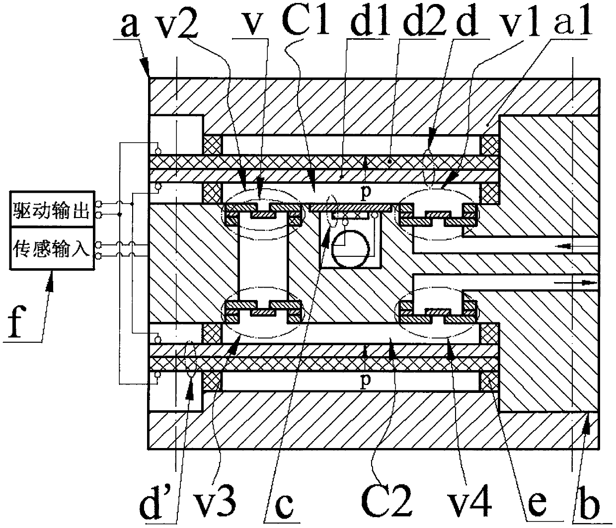
Figure 1 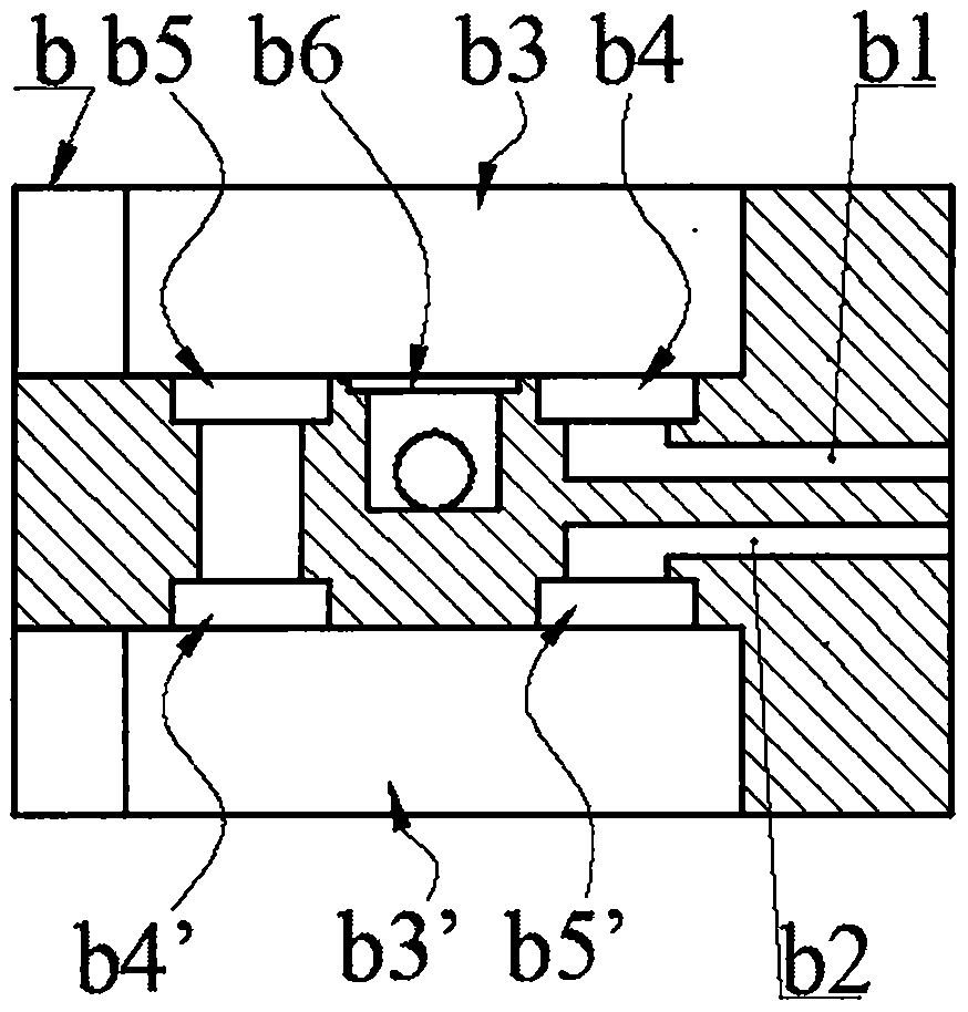
Figure 2 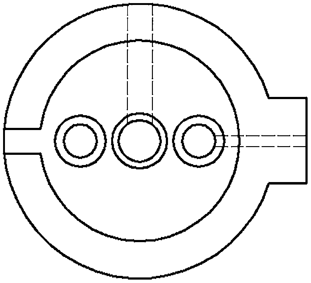
Figure 3
Abstract
Description
technical field
[0001] The invention belongs to the field of microfluid transmission and control, in particular to a self-excited pump driven by double vibrators. Background technique
[0002] As an important branch of piezoelectric actuators, piezoelectric pumps have the advantages of simple structure, small size, fast response, no electromagnetic interference, easy operation, and good flow / pressure controllability. And fuel cell fuel supply, micro-electro-hydraulic systems and other aspects have broad application prospects, and its research and development has attracted extensive attention from scholars all over the world. In order to meet the application requirements in different fields, piezoelectric pumps with various structures have been proposed. Although the structure and performance of the proposed piezoelectric pumps are quite different, they all use the bending deformation of the wafer-shaped piezoelectric vibrator under the action of an electric field to realize...
Examples
Embodiment Construction
[0017] A self-excited pump driven by double oscillators of the present invention is composed of pump cover a, pump body b, disc valve v, sensor c, upper chamber oscillator d, lower chamber oscillator d', sealing ring e, power supply f and wire group . The pump body b is provided with an inlet b1, an outlet b2, an upper body cavity b3 and a lower body cavity b3', the bottom wall of the upper body cavity b3 is provided with an upper inlet valve cavity b4 and an upper outlet valve cavity b5, and the top wall of the lower body cavity b3' The lower inlet valve cavity b4' and the lower outlet valve cavity b5' are provided, the side walls of the upper body cavity b3 and the lower body cavity b3' are provided with wiring grooves, the bottom wall of the upper body cavity b3 or the top wall of the lower body cavity b3' There is a sensor chamber b6 on the top, and a wiring hole is provided on the side wall of the sensor chamber b6; the upper inlet valve chamber b4 communicates with the i...