
Foam cutting machine
A cutting machine and foam technology, applied in metal processing and other directions, can solve the problems of low cutting precision and slow cutting efficiency, and achieve the effect of high-efficiency foam cutting ability
Patent Information
- Authority / Receiving Office
- CN · China
- Patent Type
- Applications(China)
- Current Assignee / Owner
- Publication Date
- 2019-08-30
Smart Images
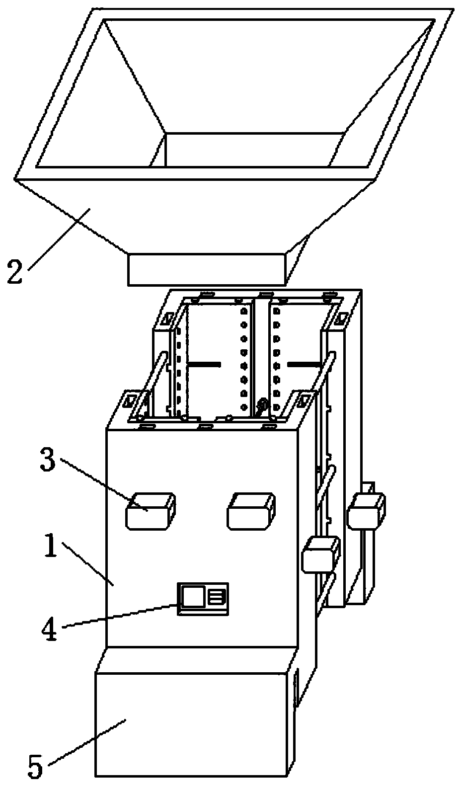
Figure 1 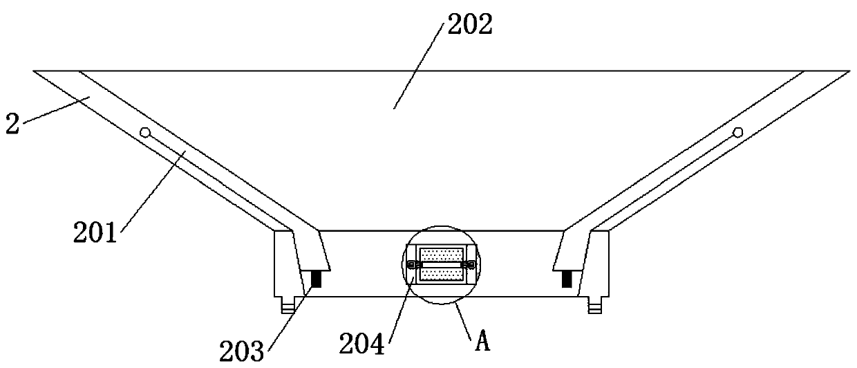
Figure 2 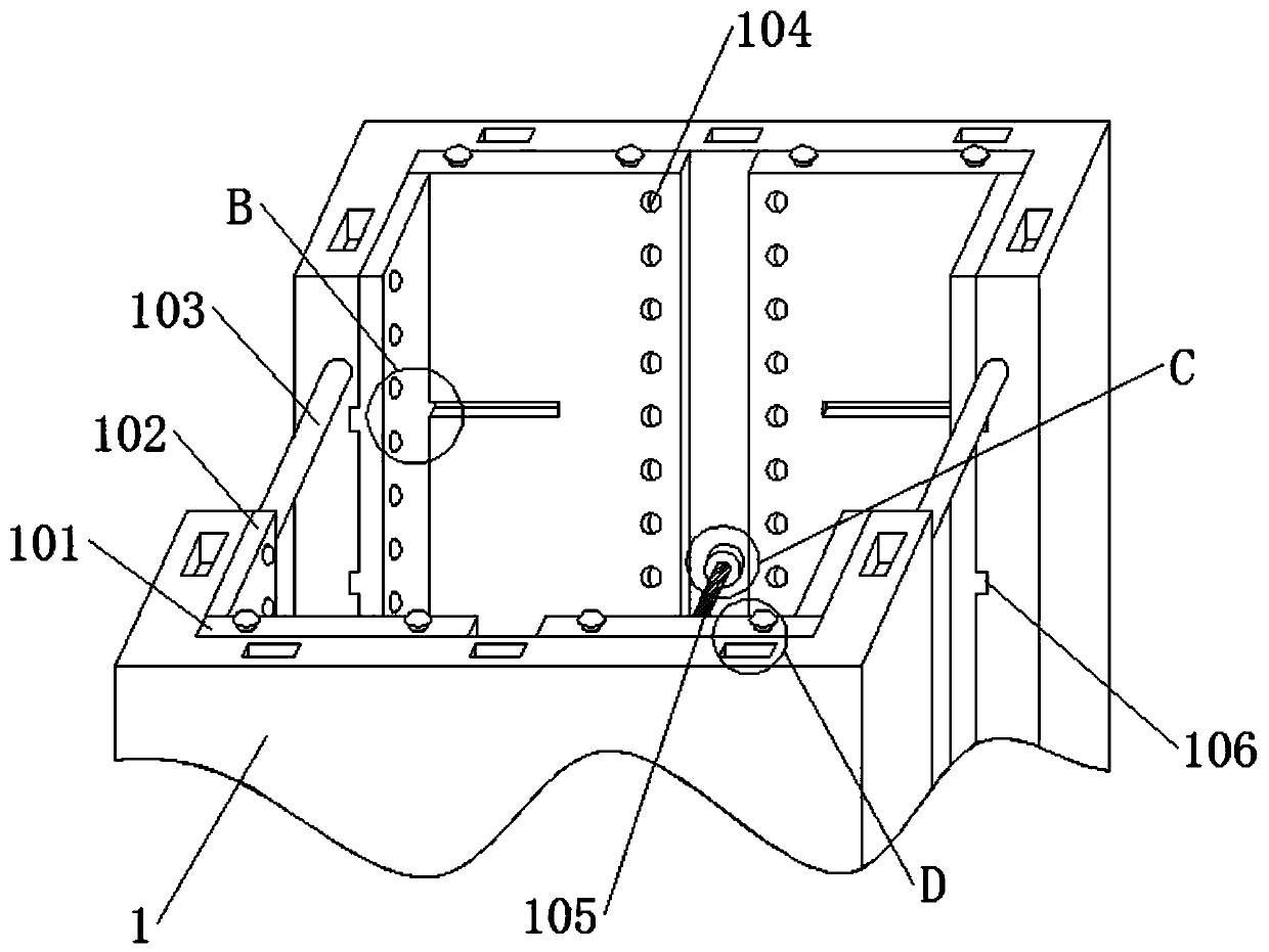
Figure 3
Abstract
Description
technical field
[0001] The invention belongs to the technical field of foam cutting equipment, in particular to a foam cutting machine. Background technique
[0002] Polystyrene foam board - also known as foam board, EPS board is made of expandable polystyrene beads containing volatile liquid foaming agent. The structural characteristics of closed cells are mainly used for building walls, roof insulation, composite panel insulation, cold storage, air conditioning, vehicle, ship insulation, floor heating, decoration and sculpture, etc. Foam materials are furniture packaging auxiliary materials, The demand is huge, the foam is used in different sizes, and the foam needs to be cut.
[0003] The existing foam boards are usually cut manually, and the cutting personnel hold one or more foam boards to cut. The cutting efficiency is slow, the cutting accuracy is low, and the demand for the existing foam boards cannot be supplied. The way to increase production is to hire a lot of ...
Examples
Embodiment Construction
[0027] It should be understood that the specific embodiments described here are only used to explain the present invention, not to limit the present invention.
[0028] See attached figure 1 To attach Figure 8 , a foam cutting machine, including: a shell 1, a horizontal limit plate 101, an outer slide rail 1011, a connecting button 1012, a vertical limit plate 102, an anti-off slide plate 1021, a ball 1022, a connecting column 103, a guide plate bead 104, Electric heating wire 105, inner slide rail 106, socket groove 107, funnel 2, movable inner plate 201, top groove 202, elastic traction rope 203, correction wheel 204, small motor 2041, rotating shaft 2042, friction wheel body 2043, hydraulic pump 3. The controller 4 and the support plate 5, the top of the housing 1 is fixedly connected with the funnel 2 through the socket groove 107, the middle parts of the front and rear ends of the housing 1 are fixedly connected with the hydraulic pump 3, and the middle part of the fron...