
Low-cost Luneberg lens antenna designed based on 3D printer
A Lumberg lens antenna, 3D printer technology, applied in the direction of antenna, antenna support/installation device, radio wave measurement system, etc., can solve the problems of complex design process and high cost, achieve low processing difficulty, reduce production cost, and simplify Effects of the design and optimization process
Patent Information
- Authority / Receiving Office
- CN · China
- Patent Type
- Applications(China)
- Current Assignee / Owner
- Publication Date
- 2019-10-15
- Estimated Expiration
- Not applicable · inactive patent
Smart Images
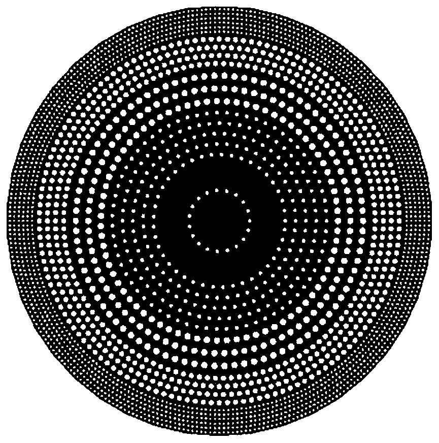
Figure 1 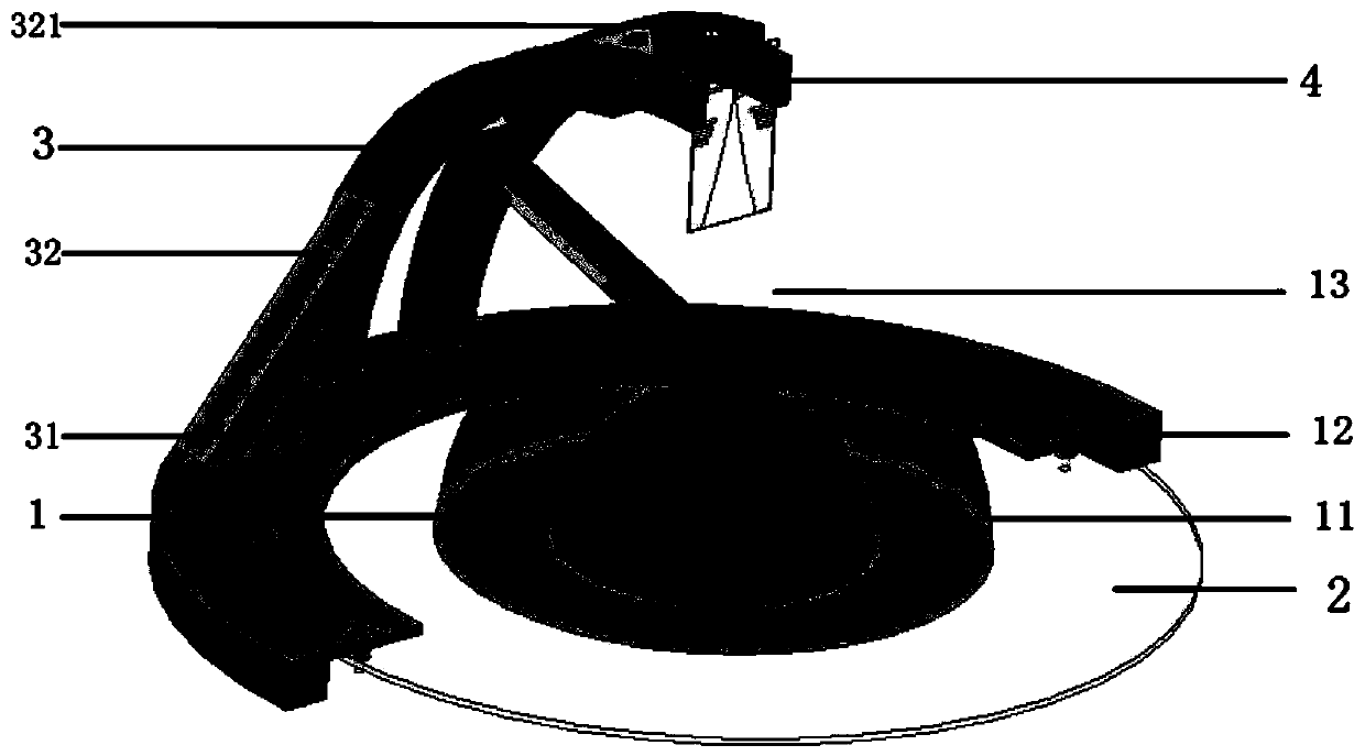
Figure 2 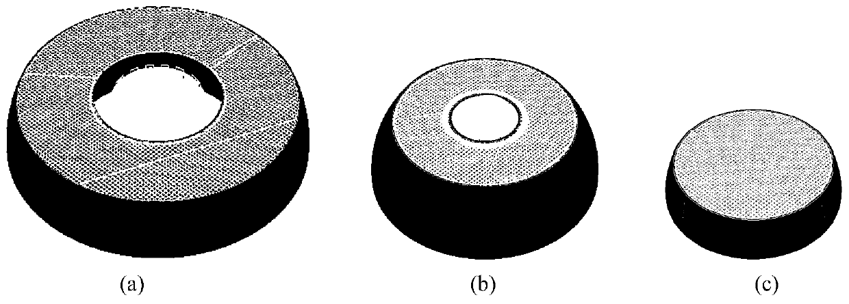
Figure 3
Abstract
Description
technical field
[0001] The invention belongs to the technical field of antennas, and in particular relates to a low-cost Luneberg lens antenna designed based on a 3D printer, which can be used for satellite communication, automobile anti-collision radar and microwave remote sensing. Background technique
[0002] The Lunberg lens antenna has the advantages of high gain, multiple beams, wide scanning angle and low cost, and it consists of two parts: a lens and a feed. in:
[0003] The lens is usually composed of concentric spherical cores with different thicknesses and different dielectric constants and N spherical shells, or a structure of concentric hemispherical cores with different thicknesses and different dielectric constants, N hemispherical shells and reflectors, and N is at least 1;
[0004] The feed source adopts a horn-type aperture antenna or a microstrip patch antenna, and is placed at the focal length of the lens. Moving the position of the feed source on the le...
Examples
Embodiment Construction
[0036] The structure and effects of the present invention will be further described in detail below in conjunction with the accompanying drawings and specific embodiments.
[0037] refer to figure 2 , this example is based on a low-cost Lunberg lens antenna designed by a 3D printer, including a hemispherical lens 1, a circular metal reflector 2, a plastic bracket 3 and a Vivaldi feed antenna 4, where the hemispherical lens 1 is fixed on the circular metal reflector 2 surface, and the center of the sphere coincides with the center of the reflector. The plastic support 3 is composed of a chassis 31 and a support 32. The support 32 is engraved with 4 pairs of radial grooves 321 with an interval of 15°. The Vivaldi feed antenna is formed by the plastic support 4. The radial groove 321 is fixed at the focal length position of the hemispherical lens 1, and the circular metal reflector 2 is fixed together with the chassis 31 of the plastic bracket.
[0038] The hemispherical lens 1...