
Permeable base course seepage diversion and drainage guiding structure applied to outdoor stone pavement
A permeable base and stone technology, applied to pavement details, side ditches/curbs, roads, etc., can solve the problems of easy damage of concrete layer and uneven operation of water pipes, etc., and achieve the effect of solving easy damage
Patent Information
- Authority / Receiving Office
- CN · China
- Patent Type
- Applications(China)
- Current Assignee / Owner
- Publication Date
- 2019-11-05
Smart Images
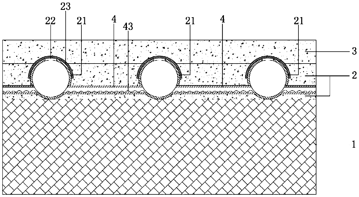
Figure 1 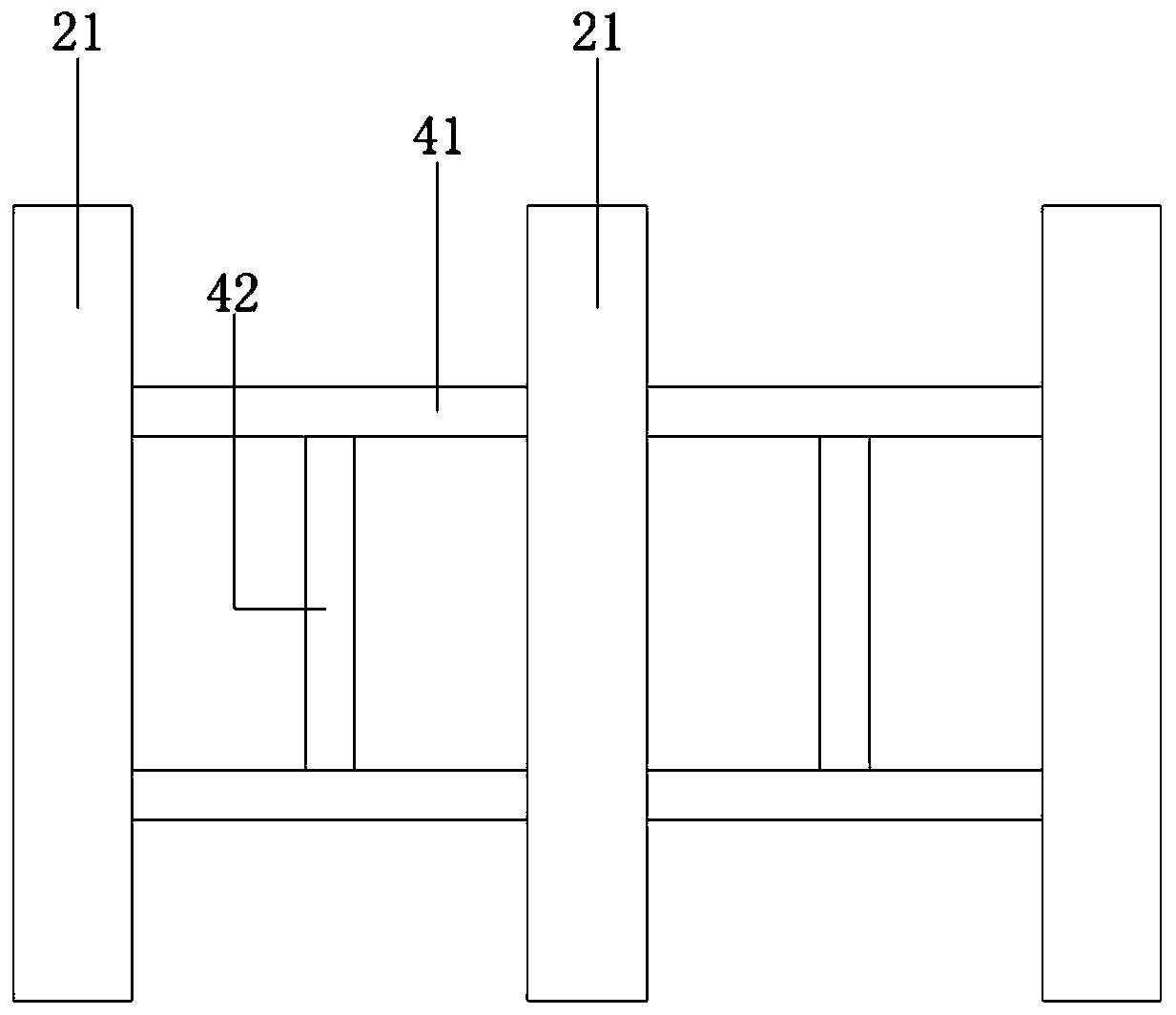
Figure 2 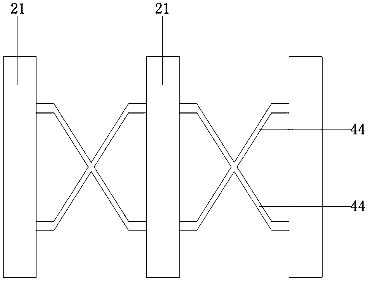
Figure 3
Abstract
Description
technical field
[0001] The invention relates to a seepage and drainage structure for a permeable base, in particular to a seepage and drainage structure for a permeable base used in outdoor stone pavement. Background technique
[0002] In recent years, problems such as the "heat island effect" of domestic cities, waterlogging caused by heavy rains, and the depletion of groundwater resources have seriously affected urban ecological construction and sustainable development. Carrying out the construction of "sponge city" is an important strategic measure to solve the above problems. An important technical means in the implementation process is the use of permeable pavement. As early as 1852, the British developed concrete without fine aggregate. In 1950, Britain applied porous asphalt pavement to airport runways. The United States began to study and design permeable concrete since the 1960s. The Netherlands began to study drainage asphalt mixtures in 1972. In addition, the ...
Examples
Embodiment 1
[0022] see Figure 1 to Figure 2 , the figure shows a permeable base layer seepage and drainage structure applied to outdoor stone pavement provided by Embodiment 1 of the present invention, which includes a ground base layer 1, a lower permeable concrete layer 2 and an upper permeable concrete layer 3, and the lower permeable layer The concrete layer 2 is a C30 permeable concrete layer, the upper permeable concrete layer 3 is a C30 permeable concrete layer, the lower permeable concrete layer 2 is fixedly laid on the ground base 1, the upper permeable concrete layer 3 is fixedly laid on the lower permeable concrete layer 2, and the lower permeable concrete layer Concrete layer 2 is embedded with a plurality of water guide pipes 21 arranged in parallel, and the top of the water guide pipes 21 is provided with a plurality of water inlet holes 22 arranged along the axial direction of the water guide pipes 21, and the top of the water guide pipes 21 is covered with water inlet The...
Embodiment 2
[0026] see Figure 1 to Figure 2 , the figure shows a water-permeable grass-roots seepage and drainage structure applied to outdoor stone pavement provided by Embodiment 2 of the present invention. This embodiment further makes the following improvements on the basis of the above-mentioned embodiments The technical scheme of the invention: two first pressure relief pipes 41 are connected through a second pressure relief pipe 42, and the second pressure relief pipe 42 is perpendicular to the first pressure relief pipe 41, which forms an I-shaped structure, which can realize The exchange of water flow and air flow between the two first pressure-discharging pipelines balances the air pressure in the entire pressure-discharging pipeline assembly.
[0027] see Figure 1 to Figure 2 , the inner wall of the first pressure discharge pipe 41 is provided with a wave-shaped first buffer layer 43, which can realize the buffering effect on the water flow, so as not to cause the instantane...
Embodiment 3
[0029] see image 3 , the figure shows a water-permeable grass-roots seepage and drainage structure applied to outdoor stone pavement provided by Embodiment 3 of the present invention. This embodiment further makes the following improvements on the basis of the above-mentioned embodiments The technical solution: the difference is that the pressure relief pipeline assembly 4 includes two X-shaped crossed third pressure relief pipes 44, and the opposite ends of the third pressure relief pipe 44 are respectively connected to two adjacent water conduits 21, which can Realize the exchange of water flow and air flow between the two first pressure-discharging pipelines, balance the air pressure in the entire pressure-discharging pipeline assembly, and save the amount of pipelines.
[0030] At the same time, the inner wall of the third pressure discharge pipe 44 is provided with a wave-shaped second buffer layer (consistent with the structure of the first buffer layer), which can real...