
Cutting chip identification method for bending unit
A bending unit, bending tool technology, applied in the direction of using optical devices, optical device exploration, safety equipment, etc.
Patent Information
- Authority / Receiving Office
- CN · China
- Patent Type
- Applications(China)
- Current Assignee / Owner
- Publication Date
- 2019-11-15
Smart Images
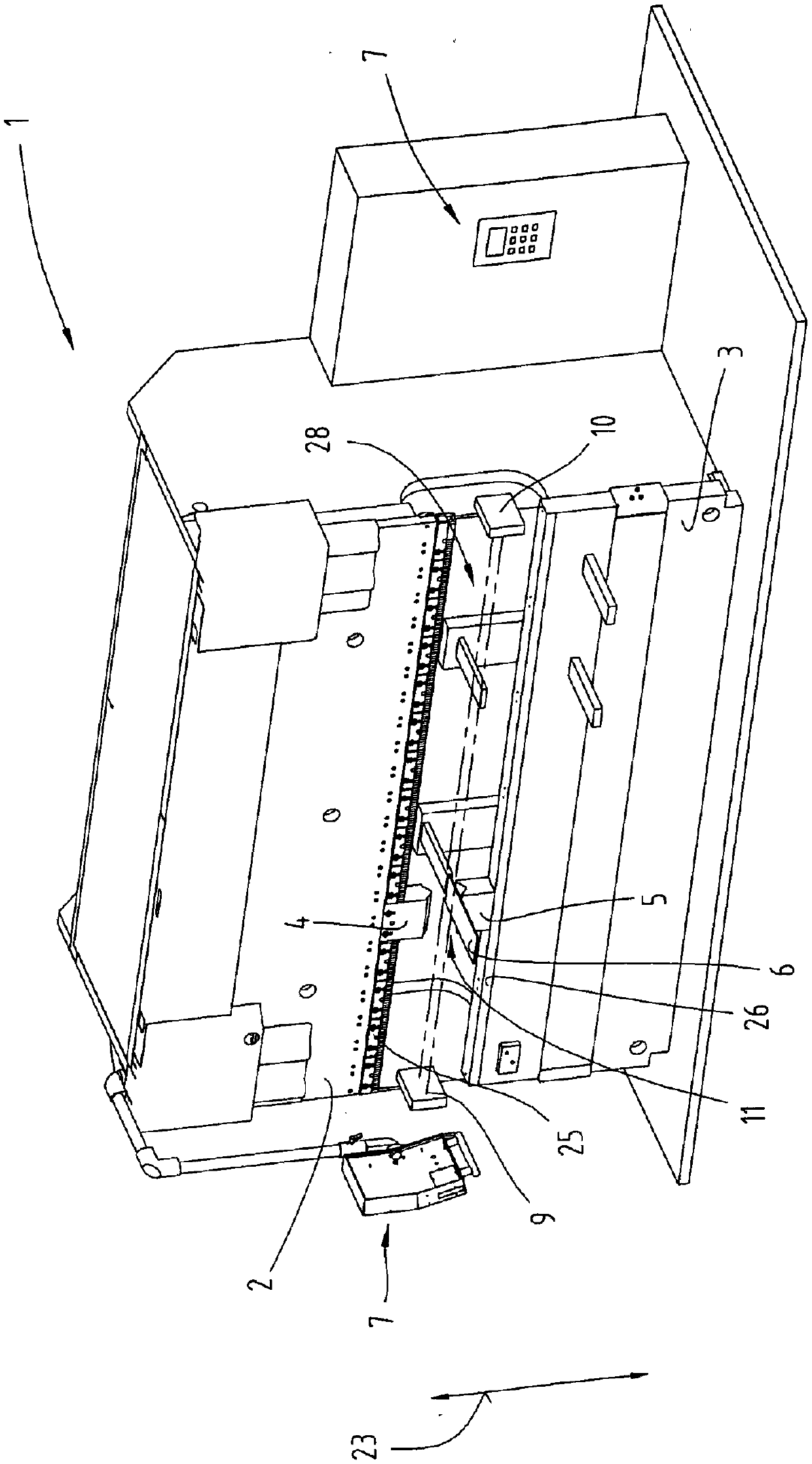
Figure 1 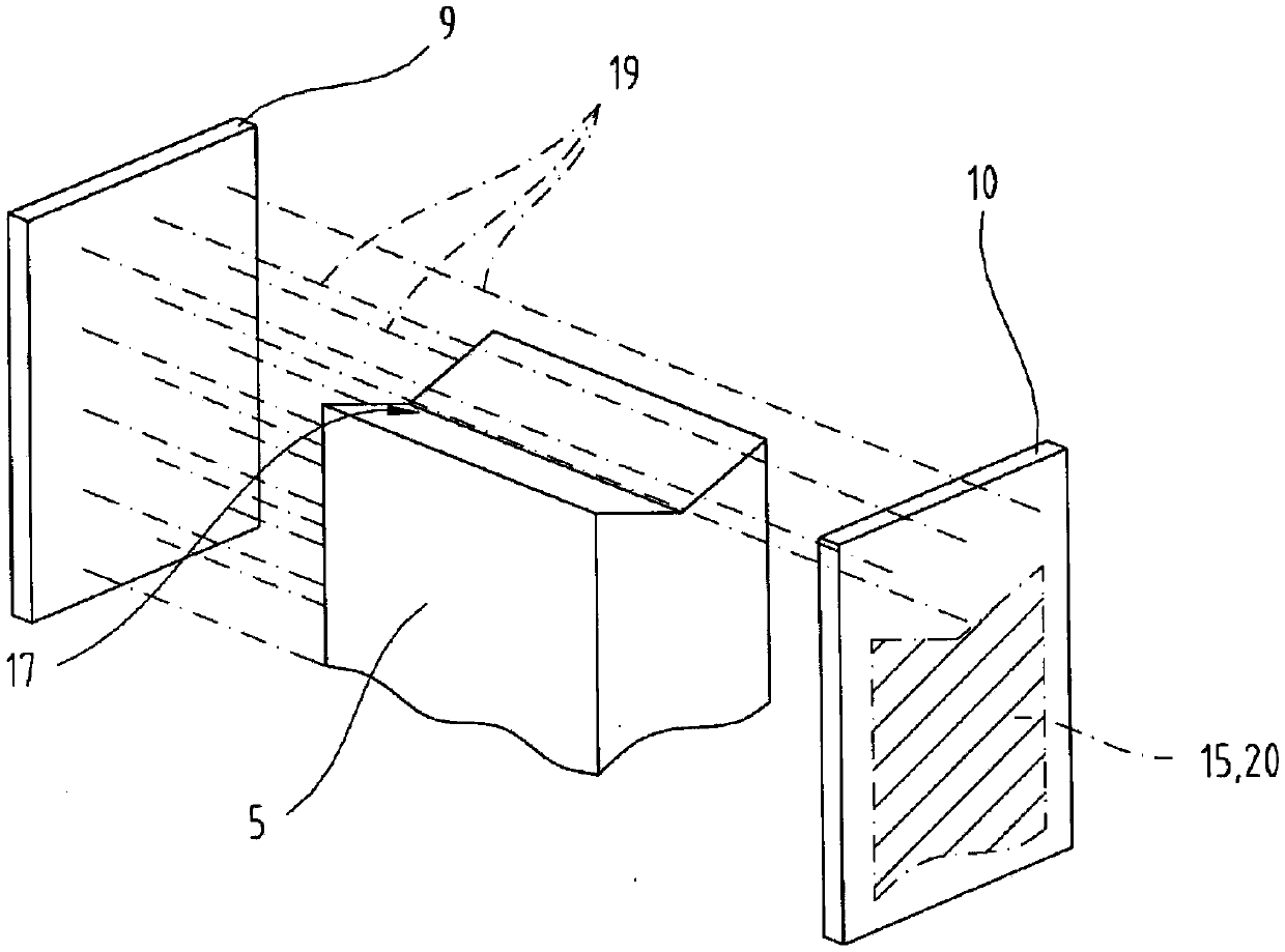
Figure 2 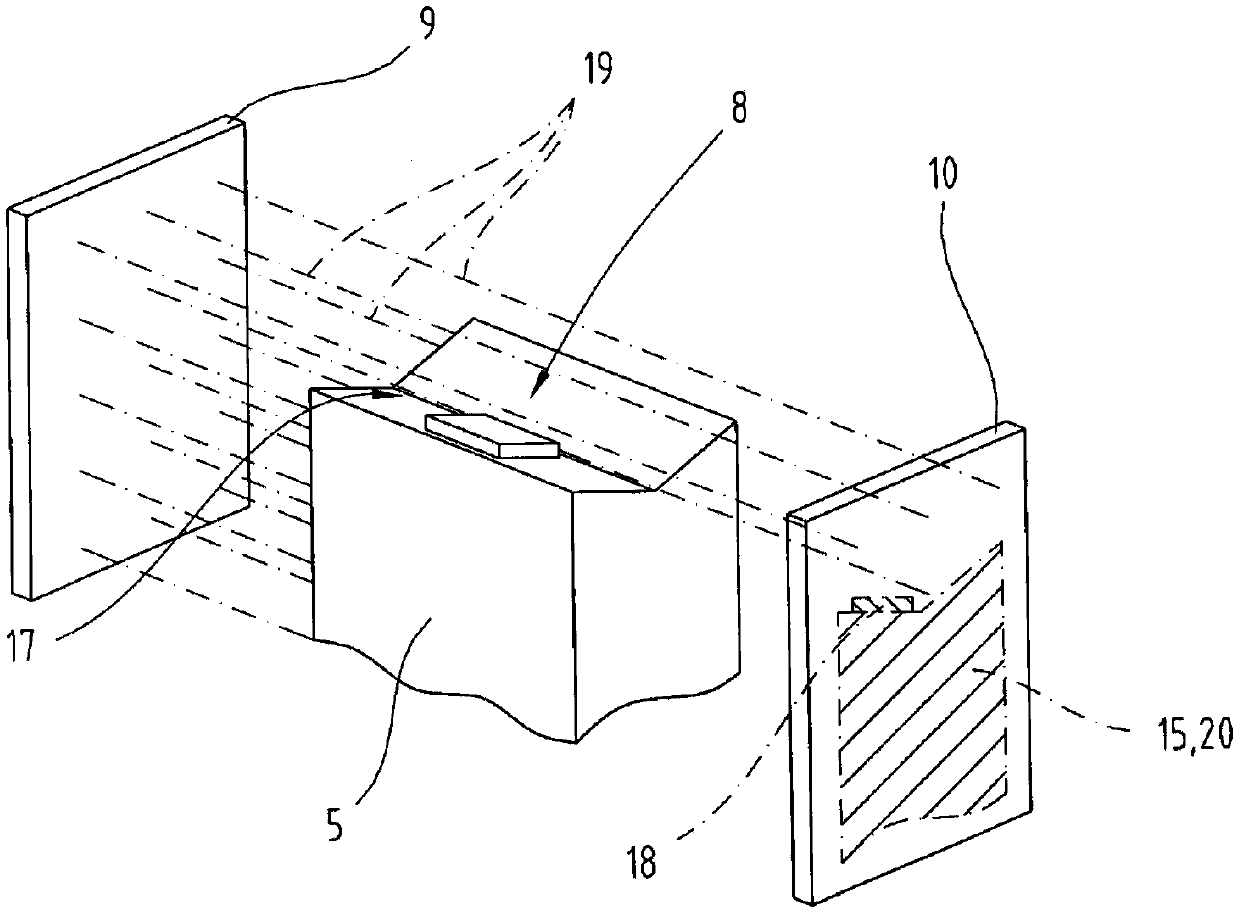
Figure 3
Abstract
Description
technical field
[0001] The invention relates to a method for detecting foreign objects, in particular cutting or punching waste, between at least one bending tool and a sheet metal part to be formed using at least one light source and at least one light sensor. Background technique
[0002] When processing laser-processed, punched or also cut sheet metal, it often happens that foreign bodies in the form of cutting or punching waste settle on the sheet metal. This foreign matter is also known as cutting or stamping debris. Due to the use of oil, said residues or foreign matter sometimes adhere very strongly to the board.
[0003] For further processing of the sheet metal, such as deep drawing, pressing or bending, such foreign bodies, such as for example cutting or punching chips, but also loose cutting or punching burrs can cause damage to the tool. In addition, such foreign matter adhering to the sheet may detach from the sheet and be transferred to the tool. If the fore...
Examples
Embodiment Construction
[0056] First of all, it should be ensured that in the differently described embodiments, the same parts have the same reference signs or the same component designations, and that the disclosure content contained in the entire description can be transferred reasonably to the components with the same reference signs or the same component names. same parts. The selected position descriptions in the description, such as for example top, bottom, side, etc., refer to the currently described and shown figures and in the event of a position change, these position descriptions can be appropriately transferred to the new position.
[0057] exist figure 1 A bending unit 1 is schematically shown in , which can be used in the method according to the invention. The bending unit 1 has a horizontal pressure beam 2 which is designed to be reciprocated in a direction of movement 23 by a drive unit not shown in detail. Upper tool 4 can be directly arranged on the pressure beam 2, or as figure...