
V-shaped filter tank with produced water tanks arranged below filter tanks and working method thereof
A filter and pool technology, applied in the direction of separation methods, chemical instruments and methods, fixed filter elements, etc., can solve the problems of V-shaped filter with large floor area, large floor area, complex pool structure, etc. Achieve the effect of reducing the amount of excavated earthwork and foundation treatment area, reducing the occupied area, and reducing project investment
Patent Information
- Authority / Receiving Office
- CN · China
- Patent Type
- Applications(China)
- Current Assignee / Owner
- Publication Date
- 2020-03-06
Smart Images
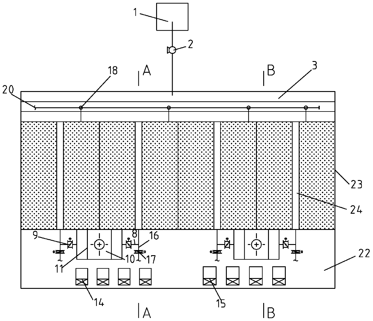
Figure 1 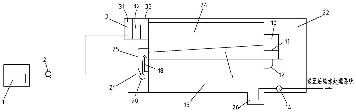
Figure 2 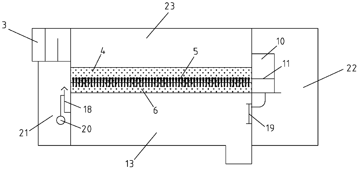
Figure 3
Abstract
Description
technical field
[0001] The invention relates to the technical field of wastewater treatment and purification, in particular to a V-shaped filter tank with a water production tank arranged below the filter tank and a working method thereof. Background technique
[0002] At present, the V-shaped filter commonly used in the wastewater treatment system of iron and steel enterprises is generally in the form of a side-by-side arrangement of the filter tank and the water production tank, that is, the water production tank is located on one side of the filter tank, and the filtered water enters the outlet tank through the filter head. Gravity flow into the production pond. After the investigation of the actual operation on the site, the above layout method has the following disadvantages: 1) The single pool area of the V-shaped filter is larger than that of the ordinary filter, and because the drainage groove in the middle occupies a part of the area, the space cannot be obtained....
Examples
Embodiment Construction
[0027] The specific embodiment of the present invention will be further described below in conjunction with accompanying drawing:
[0028] Such as Figure 1-Figure 3 As shown, a kind of water production pond of the present invention is located at the V-shaped filter pond below the filter pond, comprises the V-shaped filter pond that is made up of filter pond 23 and water production pond 13; The two ends of described filter pond 23 along the longitudinal direction are respectively The water inlet end and the water outlet end are respectively provided with a filter body on both sides of the center along the transverse direction, a water storage chamber 6 is arranged at the bottom of the filter body, and a filter head 5 is arranged on a filter plate between the water storage chamber 6 and the filter material 4; A drainage tank 24 is arranged between the pool body, and an air-water chamber 7 is arranged at the bottom of the drainage groove 24; the water storage chamber 6 and the a...