
Adjustable protecting device for pipeline flaw detector
A technology of protective devices and flaw detectors, applied in the direction of measuring devices, pipeline systems, mechanical equipment, etc., can solve problems affecting the quality of flaw detection, damage of flaw detection components dropped, inconvenient cleaning of dust and debris in pipelines, etc., to improve operational flexibility, Effects of improving quality and efficiency and preventing slippage
Patent Information
- Authority / Receiving Office
- CN · China
- Patent Type
- Applications(China)
- Current Assignee / Owner
- Publication Date
- 2020-03-17
Smart Images
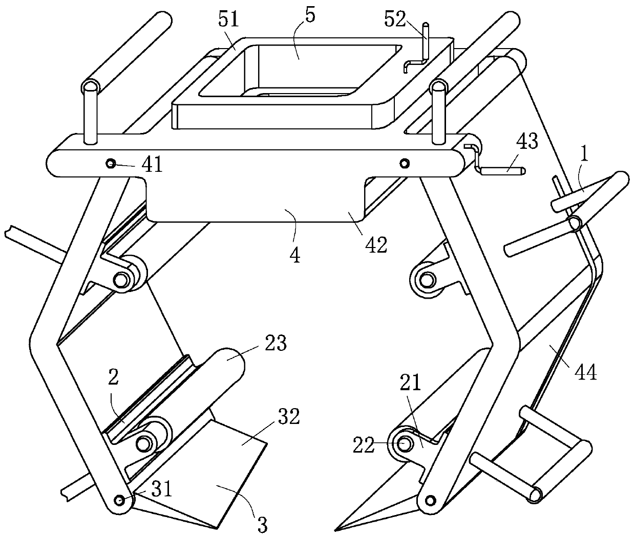
Figure 1 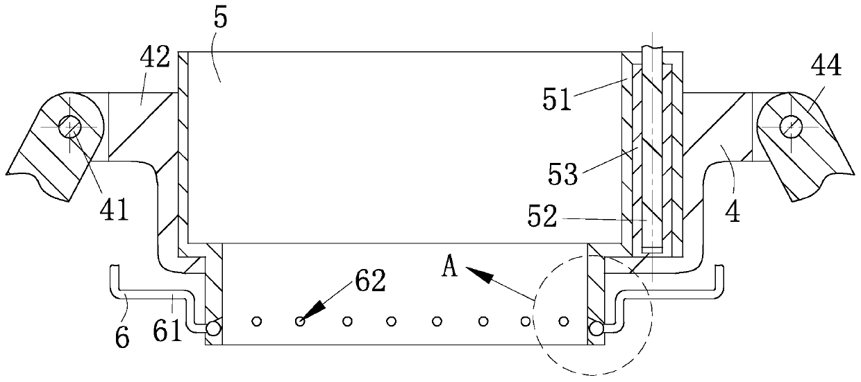
Figure 2 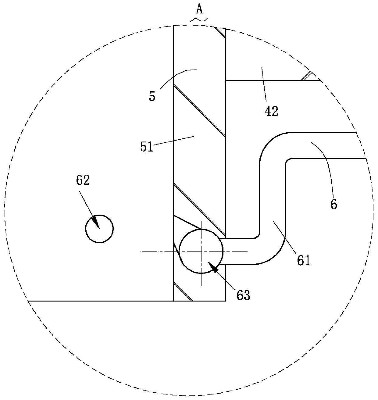
Figure 3
Abstract
Description
technical field
[0001] The invention relates to the field of pipeline flaw detectors, in particular to an adjustable protective device for pipeline flaw detectors. Background technique
[0002] The flaw detector is generally non-destructive flaw detection. The flaw detector is specially used for shipbuilding, petroleum, chemical industry, machinery, aerospace, transportation and construction and other industrial sectors to check the welding quality of materials and parts such as hulls, pipelines, high-pressure vessels, boilers, aircraft, vehicles and bridges. , and the quality of processed parts such as various light metals, rubber, ceramics, etc. In the case of performance, it is a method to detect various macroscopic defects inside or on the surface of materials, objects or equipment, and to judge their position, size, shape and type.
[0003] However, when performing flaw detection on a pipeline that has been installed with a relatively high erection height, the traditio...
Examples
Embodiment Construction
[0030] In order to make the technical means, creative features, goals and effects achieved by the present invention easy to understand, the present invention will be further described below in conjunction with specific embodiments.
[0031] like Figure 1-Figure 10 As shown, an adjustable protective device for a pipeline flaw detector according to the present invention includes a handle 1, a guiding structure 2, a cleaning structure 3, a limiting structure 4, a fixing structure 5, ash removal structure 6 and a transmission structure 7. The four guiding structures 2 for guiding are symmetrically arranged at both ends of the limiting structure 4, and the guiding structures 2 are detachably connected to the limiting structure 4; used to adjust the four A plurality of said handles 1 are equidistantly arranged on said limit structure 4 at the position of each said guide structure 2; said limit structure 4 is provided with said fixing structure 5 for adjusting the position of the fl...