
Multiple suppression method based on optimal hyperbolic integral path superposition
An integral path and multiple wave technology, applied in the field of noise suppression, to achieve the effects of improving precision and accuracy, high computing efficiency, and reducing costs
Patent Information
- Authority / Receiving Office
- CN · China
- Patent Type
- Applications(China)
- Current Assignee / Owner
- Publication Date
- 2020-06-05
Smart Images
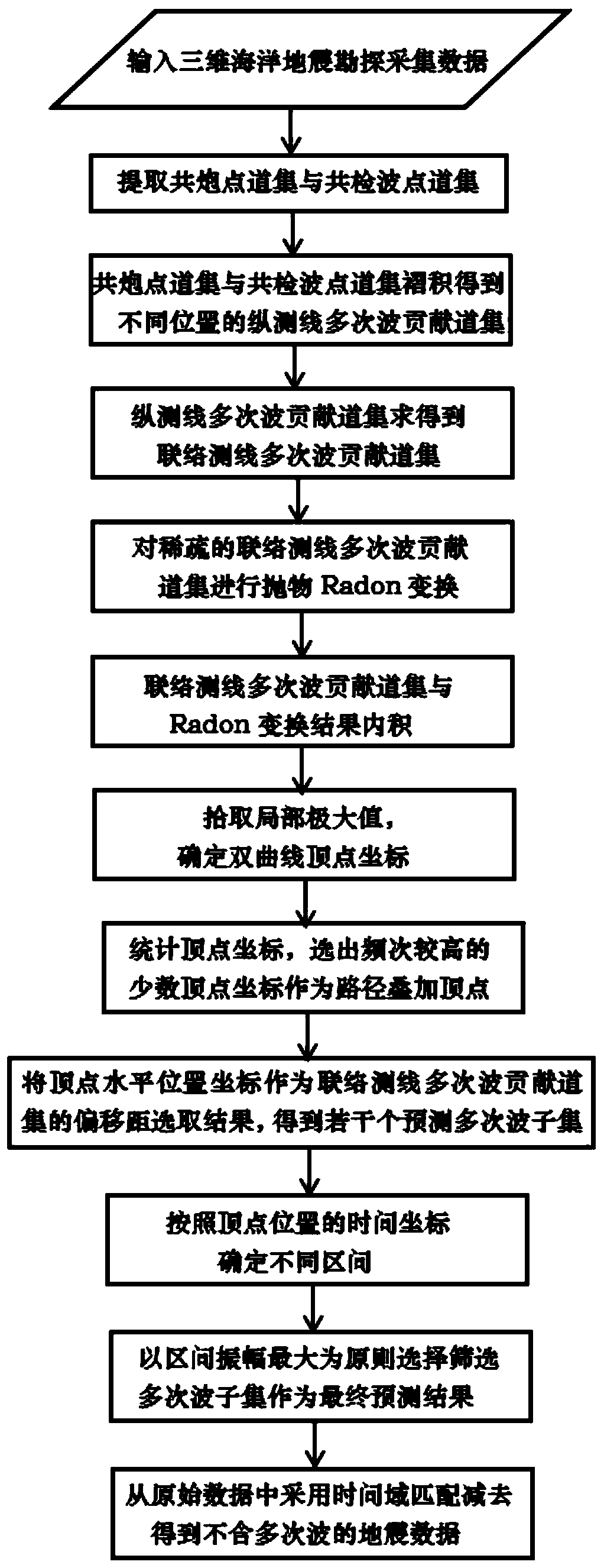
Figure 1 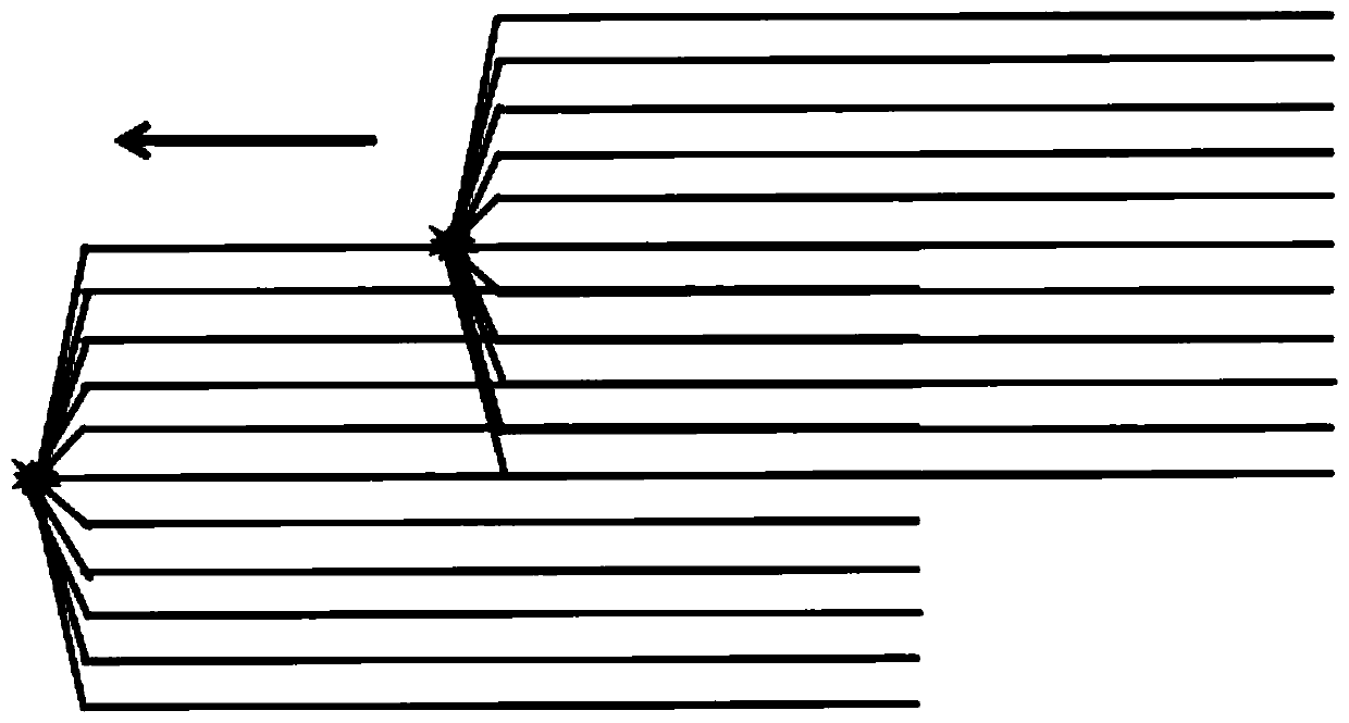
Figure 2 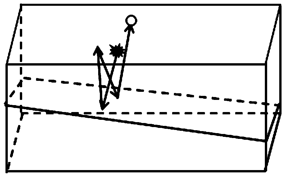
Figure 3
Abstract
Description
technical field
[0001] The invention belongs to the technical field of noise suppression in geophysical exploration, in particular to a multiple wave suppression method in marine seismic exploration, in particular to a multiple wave suppression method based on optimal hyperbolic integral path superposition. Background technique
[0002] In marine seismic exploration, multiple waves will reduce the signal-to-noise ratio of seismic data due to their periodicity and kinematic shape characteristics, and are often regarded as a coherent noise that needs to be removed. At present, the more commonly used multiple wave suppression technology is 2D SRME technology. However, when the formation is inclined, the real propagation path is a three-dimensional space function, and the 2D method cannot describe the change of the contact line direction. Therefore, the multiple wave prediction problem is transformed into 3D, and 3D SRME needs to be introduced. However, the 3D prediction is lim...
Examples
Embodiment 1
[0072] a. The simulated data model is a three-dimensional inclined formation model ( Figure 9a ). The observation system is set to 11 2000-meter-long survey lines with a distance of 100 meters and a near-parallel spread (-500m—500m). Seismic waves are excited at intervals of 25 meters at the horizontal position of the central cable, and the data are complemented by the reciprocity theorem to obtain the same seismic exploration data as the shot detection on the central survey line. Extract the gather according to the shot number (fldr, 1-81) in the track head information, and obtain the common shot point gather d(x k ,y k ,t,x s ,y s ); According to the detection number (tracl, (1-81, 1-11)), the gathers are extracted to obtain the common receiver point gather r(x r ,y r ,t,x k ,y k ), where (x k ,y k ) is any point position (shot point or receiver point), (x s ,y s ) is the shot point coordinates, (x r ,y r ) is the coordinates of the detection point, and t is t...