
A mobile phone security lifting camera
A mobile phone security and camera technology, applied in the camera, image communication, telephone structure and other directions, can solve the problems of not fully protecting the camera, large mobile phone installation space, damage to the camera, etc. Effect
Patent Information
- Authority / Receiving Office
- CN · China
- Patent Type
- Patents(China)
- Current Assignee / Owner
- Publication Date
- 2021-08-17
Smart Images
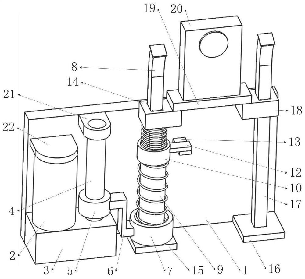
Figure 1 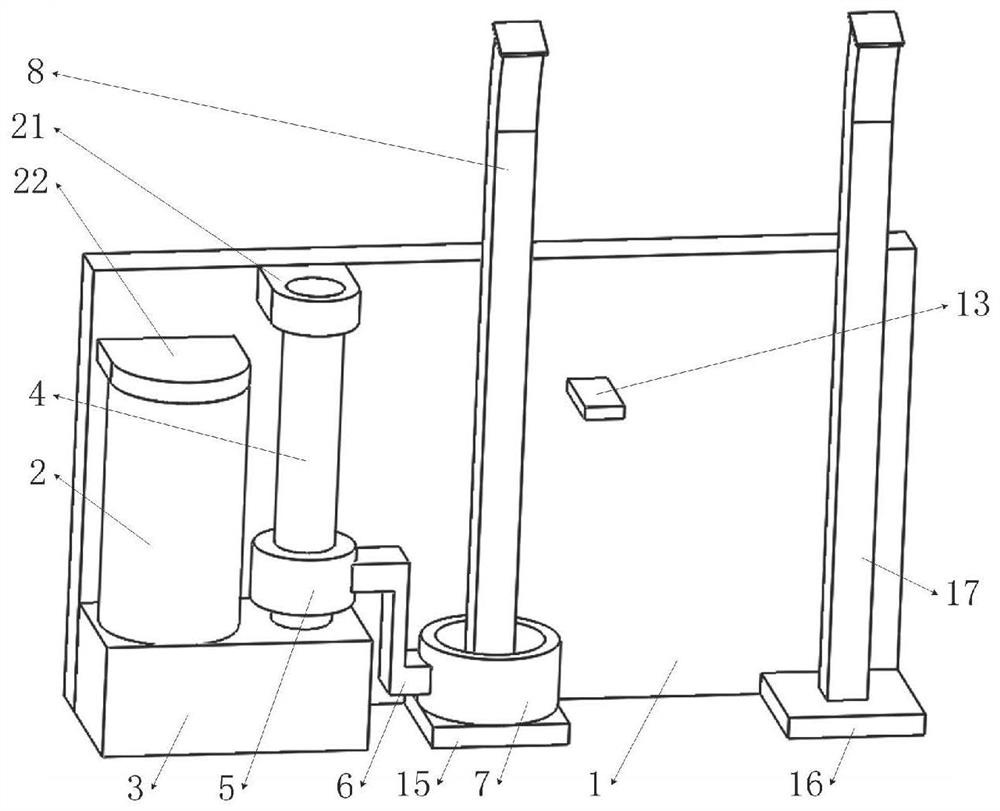
Figure 2 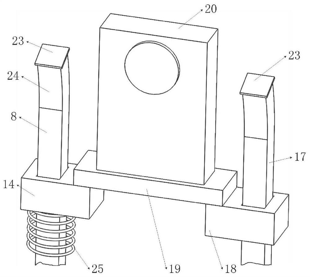
Figure 3
Abstract
Description
technical field
[0001] The invention belongs to the field of mobile phones, in particular to a mobile phone safety lifting camera. Background technique
[0002] At present, with the evolution of mobile phone aesthetics and design, there is already a mobile phone on the market that can lift the camera; the camera of this mobile phone is normally shrunk inside the body, and when it needs to be used, it stretches out the screen to take pictures; the existing The lifting method of the camera in the technology often adopts the transmission form of the screw nut to drive the camera to expand and contract.
[0003] If the existing mobile phone with the function of raising and lowering the camera accidentally drops the mobile phone when taking pictures, the camera that has protruded from the inside of the body is easily damaged by impact. In the prior art, in order to solve the problem of camera impact damage, three schemes are mainly adopted:
[0004] The first one is to control ...
Examples
Embodiment Construction
[0042] The structural proportions in the drawings of the present invention are schematic, and the structural proportions can be determined according to actual needs.
[0043] A mobile phone safety lifting camera 20, which includes electric drive, base 1, screw rod 4, nut 5, A tube 7, A square rod 8, sleeve 9, B tube 10, A slider 14, booster spring 25, Arc sheet 26, extension spring 27, sliding disc 28, stage clip 29, rack 30, gear 32, pendulum plate 33, limit plate 36, as figure 1 As shown, wherein the base 1 is fixedly equipped with an electric drive to rotate the screw 4; as figure 2 , 10 As shown, the A square rod 8 fixed on the base 1 through the A support 15 is composed of a vertical section and a curved section 24; as Figure 10 As shown, the top end of the sleeve 9 is fixed with the B cylinder 10, and the outer cylinder surface at the bottom end is provided with a mounting groove 31; as Figure 13 , 14 As shown, the limit plate 36 is fixed on the top of the notch o...