
Spray condensing device for normal-pressure heat pump evaporator
A heat pump evaporator and condensing device technology, applied in evaporators/condensers, refrigerators, refrigeration components, etc., can solve the problem of low heat transfer efficiency of the air-water partition, achieve stable condensation effect, reduce cost, and improve heat transfer efficiency high effect
Patent Information
- Authority / Receiving Office
- CN · China
- Patent Type
- Applications(China)
- Current Assignee / Owner
- Publication Date
- 2020-07-03
Smart Images
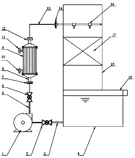
Figure 1 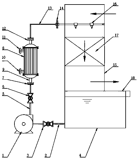
Figure 2
Abstract
Description
technical field
[0001] The invention relates to the technical field of heat pump evaporators, in particular to a spray condensing device for an atmospheric pressure heat pump evaporator. Background technique
[0002] Heat pump evaporation refers to compressing the secondary steam evaporated by the evaporator with a compressor, increasing its pressure, making its saturation temperature exceed the boiling point of the solution, and then sending it back to the heating chamber of the evaporator as heating steam. This method is called heat pump evaporation. , the use of heat pump evaporation only needs to supply heating steam during the start-up stage of the evaporator. When the operation reaches a stable level, no heating steam is needed, and only the work required to increase the pressure of the secondary steam is provided, thus saving a lot of raw steam;
[0003] The condensing device of the existing atmospheric pressure heat pump evaporator uses water vapor to exchange heat t...
Examples
Embodiment
[0033] Example: such as Figure 1-2 As shown, the present invention provides a technical solution, a spray condensing device for an atmospheric heat pump evaporator, including a spray water pump 1, the water inlet end of the spray water pump 1 is connected to a water inlet pipe 2, and one end of the water inlet pipe 2 is connected to a condensation tower 4;
[0034] The water outlet end of the spray water pump 1 is connected with the water outlet pipe 5, the middle part of the water inlet pipe 2 is embedded with the water inlet valve 3, and the middle part of the water outlet pipe 5 is embedded with the water outlet valve 6, so that the spray water pump 1 can be disassembled later for easy maintenance, and the water outlet pipe One end of 5 is connected with a water inlet flange 7, and the water inlet flange 7 is connected with the heat exchanger 8, and the bottom end of the heat exchanger 8 is provided with a water inlet pipe 9, and the water inlet pipe 9 is connected with the...