
A paint spraying device
A spraying device and paint technology, applied in the direction of spraying device, etc., can solve the problems of poor paint application effect, operator injury, low work efficiency, etc., so as to improve work efficiency, improve painting effect, and avoid repeated painting. Effect
Patent Information
- Authority / Receiving Office
- CN · China
- Patent Type
- Patents(China)
- Current Assignee / Owner
- Publication Date
- 2021-05-14
Smart Images
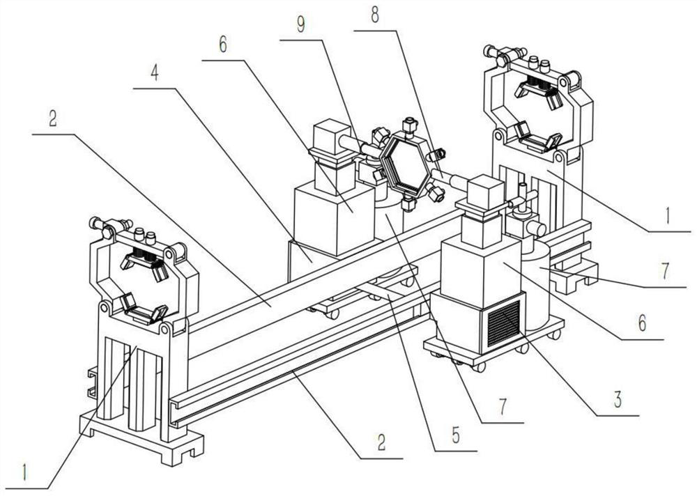
Figure 1 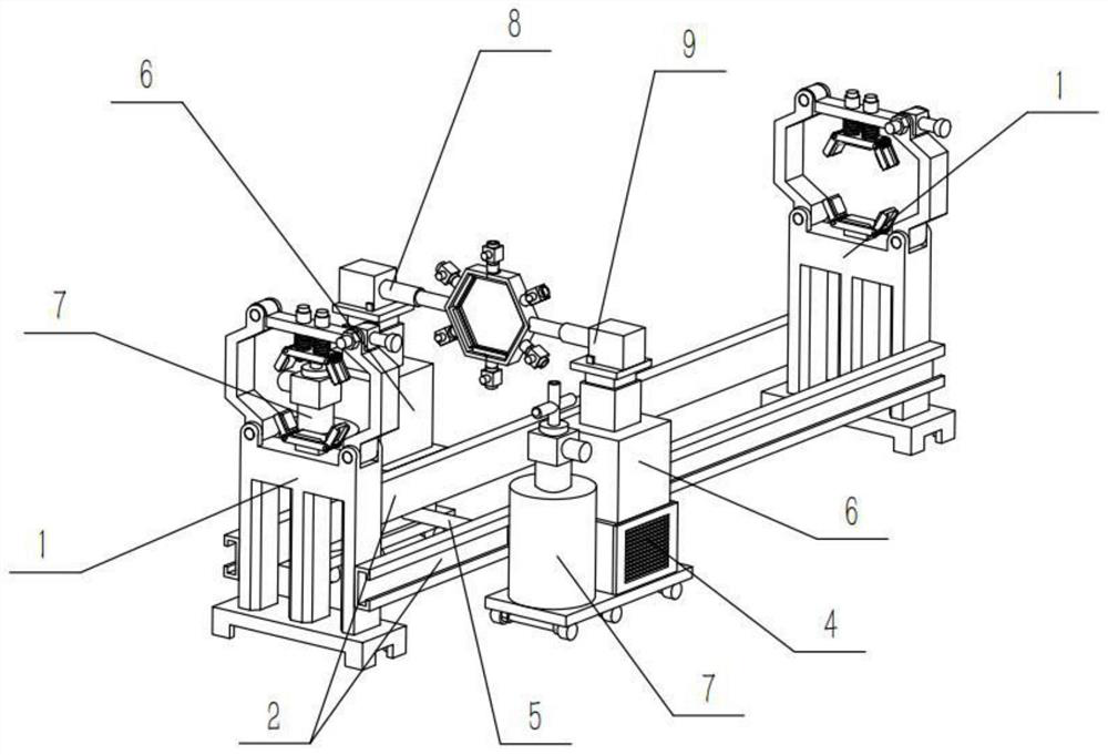
Figure 2 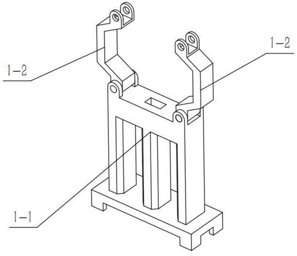
Figure 3
Abstract
Description
technical field
[0001] The invention relates to the technical field of spraying equipment, in particular to a paint spraying device. Background technique
[0002] In the process of industrial production, building manufacturing and infrastructure engineering, it is often necessary to use long or cylindrical metal profiles or wooden profiles, such as various house beams, steel frames, and roadside street lamps, etc. The exterior often needs to be sprayed with various functional paints, such as: rubber paint, insect-proof paint, paint, etc., to play the role of anti-corrosion and insect-proof, and prolong the service life of the above-mentioned profiles. However, the current painting method is mostly through manual brushing. Manual painting not only has low work efficiency, but also has poor paint application effect, and some paints have a corrosive effect on human skin, which is easy to cause injury to operators. Contents of the invention
[0003] The object of the present ...
Examples
specific Embodiment approach 1
[0042] Combine below Figure 1-19 In this embodiment, a paint spraying device includes a sliding frame 2, a driving mechanism 5, and a liquid control mechanism 6. The paint spraying device also includes a fixing mechanism 1, a left moving mechanism 3, a right moving mechanism 4, and a liquid supply mechanism. 7. The left spraying mechanism 8 and the right spraying mechanism 9, the fixing mechanism 1 is provided with two, the sliding frame 2 is provided with two, and the two ends of the two sliding frames 2 are fixedly connected to the ends of the two fixing mechanisms 1 respectively. Left and right ends, the left moving mechanism 3 and the right moving mechanism 4 are respectively fixedly connected to the left and right ends of the two sliding frames 2, and the two ends of the driving mechanism 5 are respectively arranged on the left moving mechanism 3 and the right In the moving mechanism 4, there are two hydraulic control mechanisms 6, and the two hydraulic control mechanism...
specific Embodiment approach 2
[0044] Combine below Figure 1-19 Describe this embodiment, this embodiment will further explain the first embodiment, the fixing mechanism 1 includes a support frame 1-1, a support rod 1-2, a bottom frame 1-3, a side frame 1-4, and a spring shaft 1-5 , limit bar 1-6, bolt group 1-7, top frame 1-8, slide bar 1-9 and spring 1-10, described support bar 1-2 is provided with two, two support bars 1-2 They are respectively hinged on the left and right sides of the upper end of the support frame 1-1, the bottom frame 1-3 is fixedly connected to the upper end of the support frame 1-1, and the limit rod 1-6 is hinged on the left side of the support rod 1-2. At the upper end, the bolt group 1-7 runs through the right end of the limit rod 1-6 and the upper end of the right support rod 1-2, and two of the sliding rods 1-9 are fixed, and the two sliding rods 1-9 are fixed Connected to the upper end of the top frame 1-8, and the two sliding rods 1-9 are slidably connected to the limit rod...
specific Embodiment approach 3
[0047] Combine below Figure 1-19 Describe this embodiment, this embodiment will further explain the second embodiment, the sliding frame 2 includes a sliding tube 2-1 and a sliding block 2-2, and the sliding block 2-2 is slidably connected in the sliding tube 2-1 , the two ends of the two sliding tubes 2-1 are respectively fixedly connected to the left and right sides of the middle part of the two support frames 1-1, and the two sliding blocks 2-2 are respectively connected with the left moving mechanism 3 and the right moving mechanism 4 Fixed connection.