
A swirling air inlet porous medium burner for microthermophotoelectricity
A porous medium, micro-thermal photoelectric technology, applied in the direction of gas fuel burners, burners, combustion types, etc., can solve the problems of uneven temperature distribution, low energy conversion rate, low combustion efficiency, etc., to reduce activation energy, combustion Full and complete combustion effect
Patent Information
- Authority / Receiving Office
- CN · China
- Patent Type
- Patents(China)
- Current Assignee / Owner
- Publication Date
- 2022-07-22
Smart Images
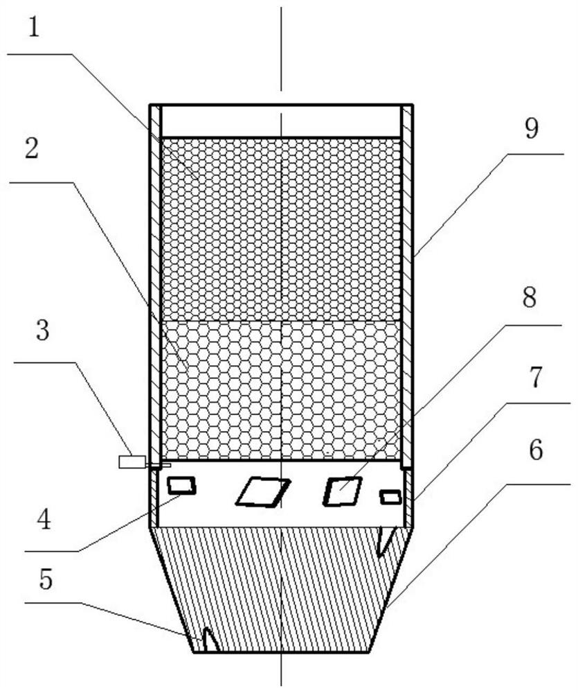
Figure 1 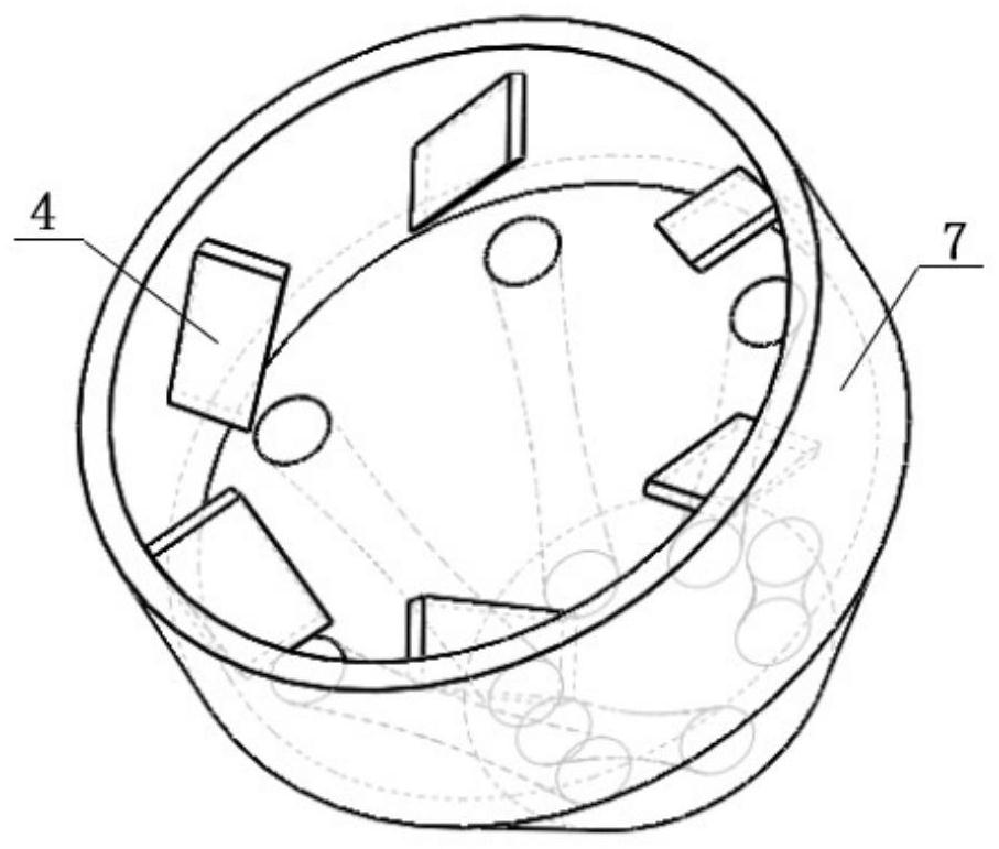
Figure 2 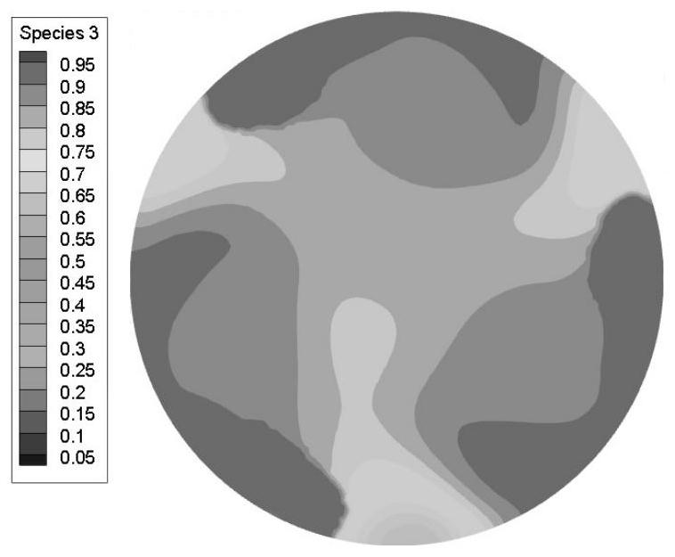
Figure 3
Abstract
Description
technical field
[0001] The invention relates to the technical field of micro-scale thermo-photoelectric energy conversion, in particular to a swirling air inlet porous medium burner for micro-thermo-photoelectricity. Background technique
[0002] With the continuous development of micro-electro-mechanical systems (MEMS) and the continuous improvement of the micro-combustion theory, people are paying more and more attention to the field of micro-energy. become the focus of current research. The basic principle of the micro-thermal photovoltaic system is to make the fuel burn in the burner to generate chemical energy, generate radiation on the wall of the burner, and then generate electricity through the photovoltaic cell. Because the scale of the entire combustion reaction is very small, there will be some problems that are different from traditional burners. First of all, because the surface-to-body ratio of the micro-combustion chamber is too large, the heat loss on the wa...
Examples
Embodiment Construction
[0024] The present invention will be further described below with reference to the accompanying drawings and specific embodiments, but the protection scope of the present invention is not limited thereto.
[0025] like figure 1 and figure 2 As shown, the swirling inlet porous media burner for microthermophotoelectricity according to the present invention includes an inlet zone 6, a combustion zone 9 and a premix zone 7, and the premix zone 7 is located in the inlet zone 6 Between the combustion zone and the combustion zone 9, the shape of the intake zone 6 is an inverted truncated cone, and at least six intake passages 5 are evenly distributed in the intake zone 6, and the inlet and outlet of any one of the intake passages 5 are at Offset in the circumferential direction, the inclination angle of the axis of the intake duct 5 is 20°~60°, that is, if the inlet of the intake channel 5 is at 0 degrees in the circumferential direction of the small end face of the truncated cone,...