

Chemical fiber textile machine
A textile machine and chemical fiber technology, applied in textiles, textiles, papermaking, knitting, etc., can solve problems such as staff injury, expansion of textile machine fires, and production line fires
Patent Information
- Authority / Receiving Office
- CN · China
- Current Assignee / Owner
- Publication Date
- 2020-10-30
- Estimated Expiration
- Not applicable · inactive patent
Smart Images
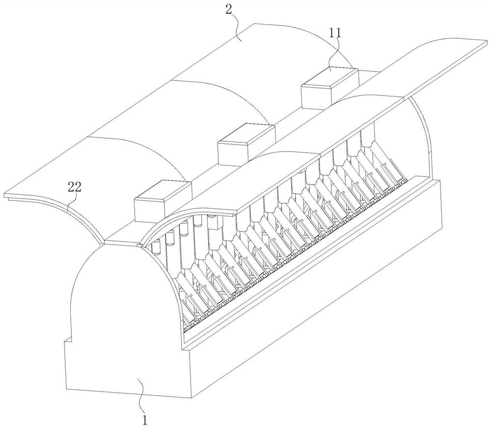
Figure 1 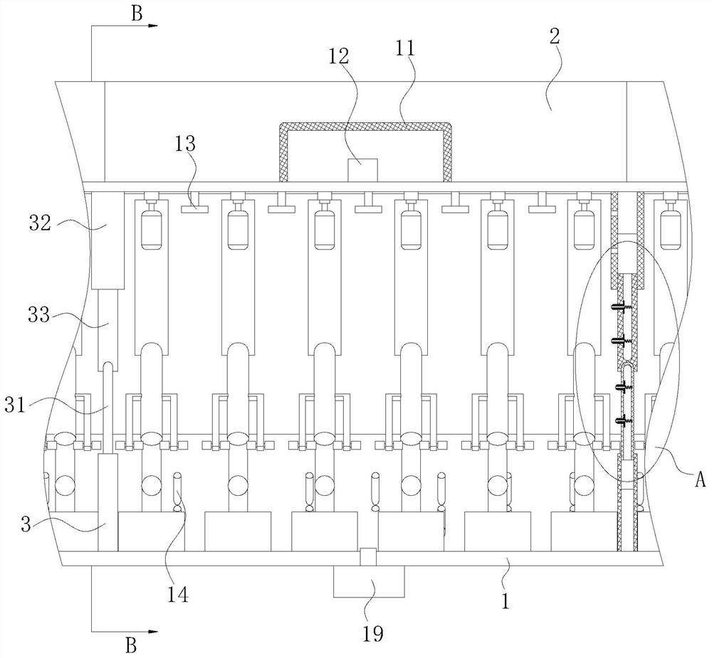
Figure 2 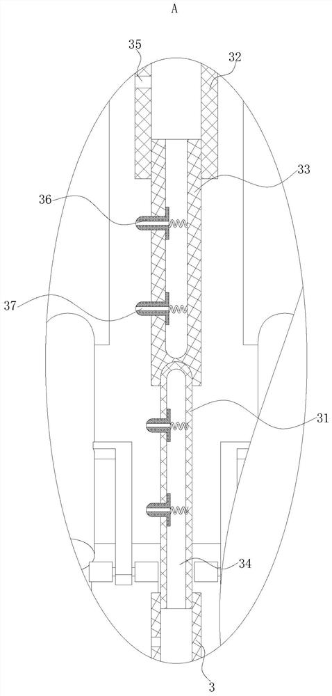
Figure 3
Abstract
Description
technical field
[0001] The invention belongs to the technical field of textile machines, in particular to a chemical fiber textile machine. Background technique
[0002] Textile machine, also known as spinning machine, loom, cotton spinning machine, etc., textile machine is the full name of a tool that processes raw materials such as thread, silk, and hemp into silk thread and then weaves it into cloth, such as spinning pendant, spinning wheel, spindle, and pedal loom. There are also modern mechanical looms, modern numerically controlled automatic looms, and various mechanical equipment required to process natural fibers or chemical fibers into textiles. In a broad sense, textile machinery also includes chemical machinery for the production of chemical fibers. Textile machinery is the textile industry. The means of production and material basis, its technical level, quality and manufacturing cost are directly related to the development of the textile industry. Textile machiner...
Examples
Embodiment Construction
[0029] use Figure 1-Figure 5 A chemical fiber spinning machine according to an embodiment of the present invention will be described as follows.
[0030] Such as Figure 1-Figure 5 As shown, a chemical fiber textile machine according to the present invention includes a body 1 and a machine cover 2; spinning equipment is installed in the cavity of the body 1; Evenly arranged electric rotating shafts; each of the electric rotating shafts is fixedly connected to the machine cover 2, and the cover 2 is arc-shaped design; the top end surface of the body 1 is fixedly connected with a uniformly arranged storage box 11, and the storage box 11 are all placed in the centerline position of the cover on the opposite side; gas and liquid carbon dioxide are all housed in each of the storage boxes 11; a pressure device 12 is fixedly connected in each of the storage boxes 11, and The pressure devices 12 are all electrically connected to the controller through wires; the inner surface of th...