
Split type mould structure for bent beam processing
A split-type, curved-beam technology, applied in the direction of forming tools, manufacturing tools, metal processing equipment, etc., can solve the problems of high production cost, low production efficiency, poor versatility, etc., to reduce the weight of the mold, ensure the correct position, reduce the The effect of labor intensity
Patent Information
- Authority / Receiving Office
- CN · China
- Current Assignee / Owner
- Publication Date
- 2020-11-27
Smart Images
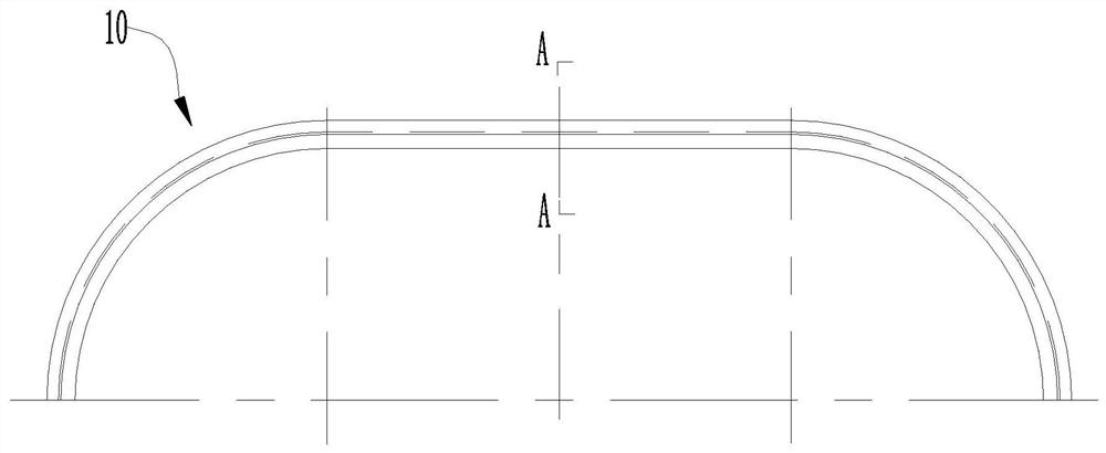
Figure 1 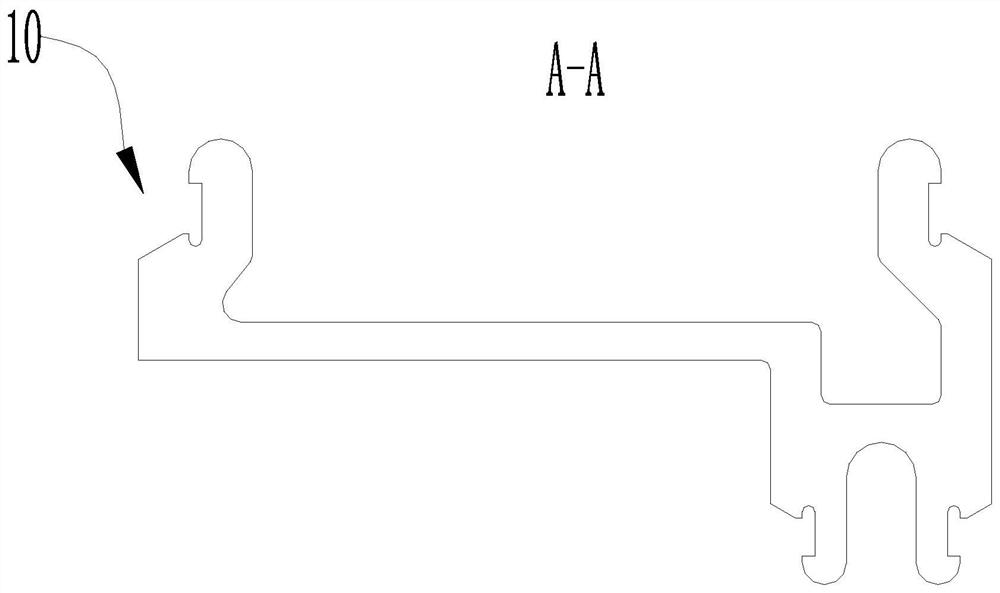
Figure 2 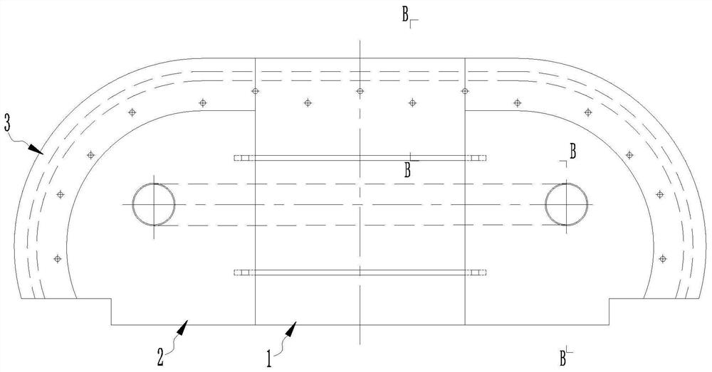
Figure 3
Abstract
Description
technical field
[0001] The invention relates to the technical field of rail vehicle bending beam processing, in particular to a split mold structure for bending beam processing. Background technique
[0002] At this stage, rail vehicles, especially urban rail and railway rail vehicles, require large parts such as roof curved beams, middle curved beams, and side columns, and such parts are due to materials (carbon steel, stainless steel, aluminum alloy) ) are different, multiple sets of molds are required to cooperate during processing and molding. However, the curved beam mold used at this stage has the same radian and a cross-section distance from one set of molds. This kind of integral mold has the following disadvantages:
[0003] 1. The production and processing of the overall mold is difficult and the production cost is high;
[0004] 2. A set of tires can only process the middle curved beam with the same radian and one section distance, which has poor versatility and...
Examples
Embodiment Construction
[0062] In order to enable those skilled in the art to better understand the technical solutions of the present invention, the present invention will be further described in detail below in conjunction with the accompanying drawings.
[0063] see Figure 3 to Figure 9 shown;
[0064] The split mold structure for bending beam processing of the present invention, the mold structure comprises:
[0065] front panel 1;
[0066] Rear plate group 3; and
[0067] Stretch bending tires 2 integrated between the front plate 1 and the rear plate group 3;
[0068] The front plate 1 and the stretch-bending tire 2 are fastened and connected by screws 4;
[0069] The rear plate group 3 and the stretch-bending tire 2 are fastened and connected by screws 4;
[0070] The rear plate group 3 includes two symmetrically arranged rear plates 301, and the distance between the two rear plates 301 is adjusted to fit curved beams 10 of different lengths;
[0071] The ends of the front plate 1 , the ...