
Concrete pouring mechanism
A technology of concrete and mixing tanks, which is applied in the direction of building construction, construction, and building materials processing. It can solve problems such as the lack of working radius of concrete pumping, time-consuming and laborious operation of concrete, etc., to achieve easy control and improve stability. Effect
Patent Information
- Authority / Receiving Office
- CN · China
- Patent Type
- Applications(China)
- Current Assignee / Owner
- Publication Date
- 2020-12-11
Smart Images
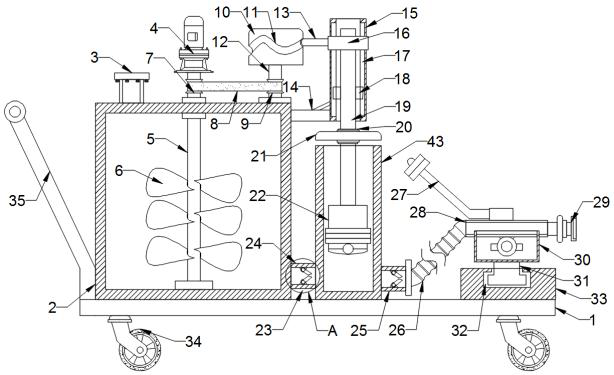
Figure 1 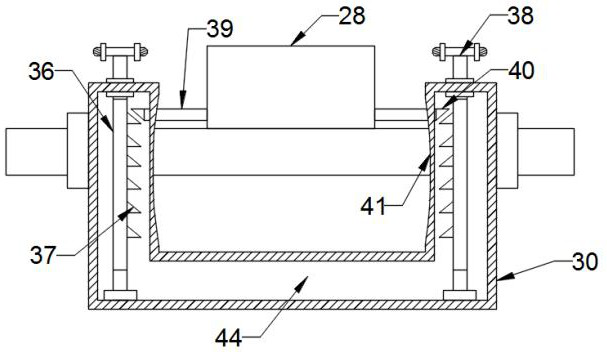
Figure 2 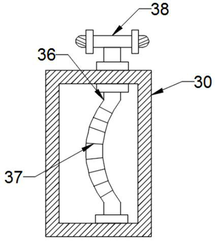
Figure 3
Abstract
Description
technical field
[0001] The invention relates to the technical field of civil engineering construction, in particular to a concrete pouring mechanism. Background technique
[0002] Concrete pouring refers to the process of pouring concrete into the mold and filling it densely. In civil engineering construction such as buildings and bridges, concrete and other materials are poured into the formwork to form a predetermined shape, but the density and strength of concrete determine the bearing capacity of the structure and major factor of security. In order to effectively control the concrete strength and construction quality, commercial concrete and its supporting pumping technology have been widely used in the industry. However, the complexity of some concrete structures makes it impossible for the concrete pumping vehicle or the working surface of the system to reach the pouring site. However, if commercial concrete and pumping trucks are still used for local construction of ...
Examples
Embodiment 1
[0027] refer to Figure 1-7, including a base 1, the top side of the base 1 is fixedly connected with a stirring box 2, and the bottom of the stirring box 2 is fixedly connected with the top of the base 1, and the top of the stirring box 2 is fixedly connected with a drive motor 4 through bolts, and the stirring box 2 The inner cavity is provided with a stirring rod 5, and the outer wall of the stirring rod 5 is fixedly connected with several stirring blades 6, the top of the stirring rod 5 runs through the top of the stirring box 2 through a bearing sleeve, and the extension part of the stirring rod 5 is sleeved with a first pulley 7. The output shaft of the drive motor 4 is connected to the top of the stirring rod 5 by transmission. The bottom end of the stirring rod 5 is rotationally connected to the bottom of the inner cavity of the stirring box 2 through a rotating shaft. One side of the stirring box 2 is provided with an extrusion pipe 43, and the The bottom end of the o...
Embodiment 2
[0029] refer to figure 1 and 5 -7, the top of the mixing box 2 is provided with a first rotating rod 12, and the second pulley 9 is sleeved on the first rotating rod 12, and the second pulley 9 and the first pulley 7 are wound and connected by a belt 8, the first The bottom end of the rotating rod 12 is rotationally connected to the top of the mixing box 2 through a rotating shaft, and the top of the first rotating rod 12 is fixedly connected with a cylindrical block 10, and the side of the outer wall of the mixing box 2 close to the extrusion pipe 43 is fixedly connected with a support plate 14 , the side of the support plate 14 close to the extrusion pipe 43 is fixedly connected with a slide plate 15, the inside of the slide plate 15 is provided with a slide bar 19, and both sides of the slide bar 19 are fixedly connected with a slide block 18, and the slide block 18 passes through the slide rail 17 Slidingly connected with the inner wall of the slide plate 15, the inner ca...
Embodiment 3
[0031] refer to Figure 1-4 , the inside of the U-shaped plate 30 is provided with an operating cavity 44, the inner cavity of the operating cavity 44 is provided with a second rotating rod 36 on both sides, and the middle part of the second rotating rod 36 is an arc structure, and the bottom of the second rotating rod 36 The end is rotationally connected between the bottom of the operating chamber 44 and the operating chamber through a rotating shaft, and the top of the second rotating rod 36 runs through the top of the vertical section of the U-shaped plate 30 through a bearing sleeve, and the extension end of the second rotating rod 36 is fixedly connected with The handle 38 and the connecting pipe 28 are fixedly connected to the limiting plate 39 on both sides near the inner wall of the U-shaped plate 30, and the end of the limiting plate 39 away from the connecting pipe 28 runs through the inner wall of the U-shaped plate 30 through the notch 41, and the limiting plate 39 ...