
Ultra-wideband millimeter-wave high-power planar film load
A millimeter-wave, high-power technology, applied in waveguide-type devices, electrical components, circuits, etc., can solve problems such as difficulty in meeting millimeter-wave high-power planar loads, patch loads being difficult to apply to millimeter-wave frequency bands, and increasing processing difficulty and cost. , to achieve the effect of improving the total power capacity, light weight and compact structure
Patent Information
- Authority / Receiving Office
- CN · China
- Patent Type
- Applications(China)
- Current Assignee / Owner
- Publication Date
- 2021-02-23
- Estimated Expiration
- Not applicable · inactive patent
Smart Images
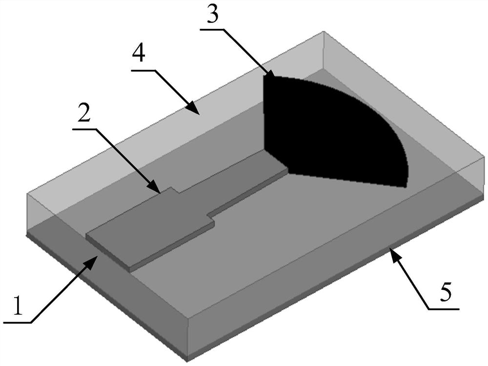
Figure 1 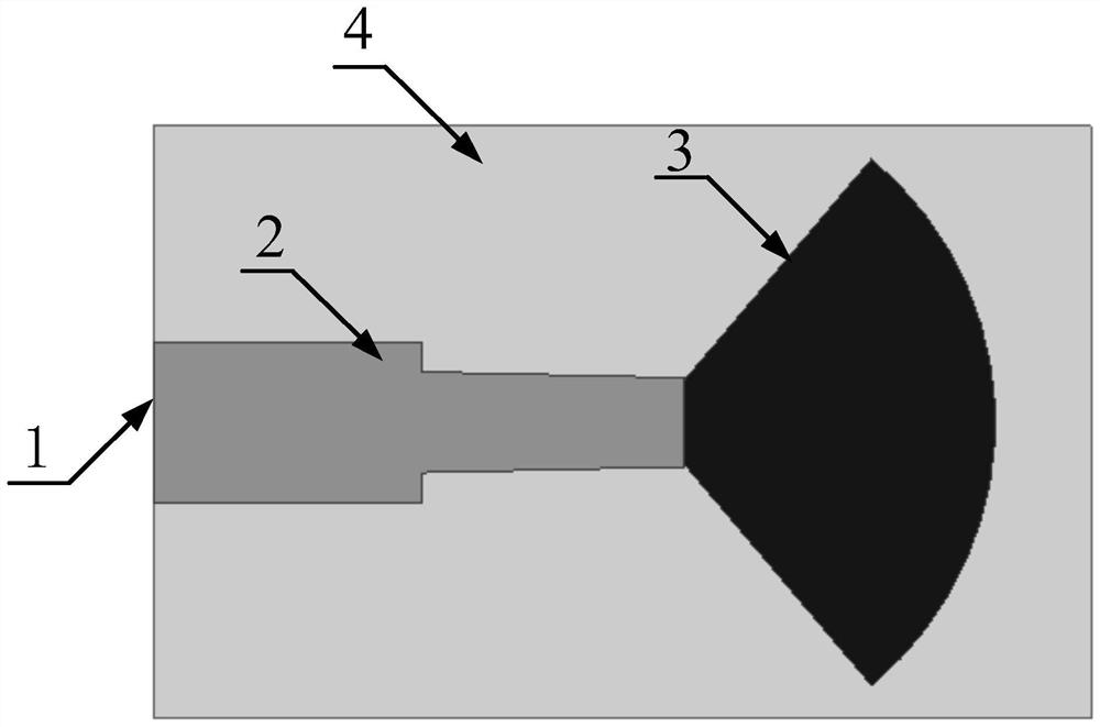
Figure 2 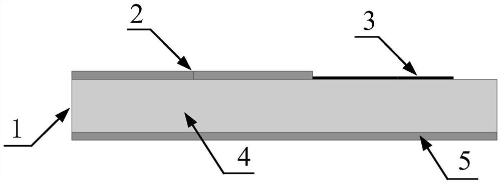
Figure 3
Abstract
Description
technical field
[0001] The invention relates to an ultra-broadband high-power film load mainly used in the technical field of millimeter wave communication equipment and radio amplifiers. Background technique
[0002] The millimeter-wave load is one of the important components in the millimeter-wave circuit. It is mainly used to realize the reflection-free matching of the transmission line, and its performance directly determines the performance of the millimeter-wave circuit. It is widely used in millimeter-wave circuits such as power combining systems, antenna feed networks, and couplers.
[0003] Millimeter wave loads are mainly divided into waveguide type and planar type. The waveguide load has two structures: rectangular waveguide load and coaxial load. Among them, the rectangular waveguide load has a high rated power and is suitable for high-power application systems. The coaxial load has a small rated power and is easy to use and is suitable for millimeter wave frequ...
Examples
Embodiment Construction
[0019] refer to Figure 1-Figure 3 . In the preferred embodiment described below, an ultra-wideband millimeter-wave high-power planar film load includes: a metal ground 5 arranged at the bottom of the dielectric substrate 4 and an input electrode 2 resistive film arranged on the dielectric substrate 4. One end is connected to the input The electrode 2 is connected and the other end is open in a fan-shaped structure. The input electrode 2 is connected to the fan-shaped resistive film through a microstrip impedance line, and a single-port thin film circuit is formed based on the fan-shaped resistive film. The radio frequency signal is fed from the input microstrip port 1 to the input electrode 2, through The microstrip impedance line enters the range of the sector-shaped resistive film, and guides the radio frequency signal to be transmitted from the end of the input electrode (2) to the open circuit end of the sector-shaped resistive film, so as to realize ultra-broadband match...