
Automatic replacement device for new energy sky train power battery pack
A power battery pack and automatic replacement technology, applied in transportation and packaging, charging stations, electric vehicles, etc., can solve the problems of low replacement efficiency, frequent replacement of battery packs, unfavorable and efficient switching of power sources, etc.
Patent Information
- Authority / Receiving Office
- CN · China
- Current Assignee / Owner
- Publication Date
- 2021-04-20
- Estimated Expiration
- Not applicable · inactive patent
Smart Images
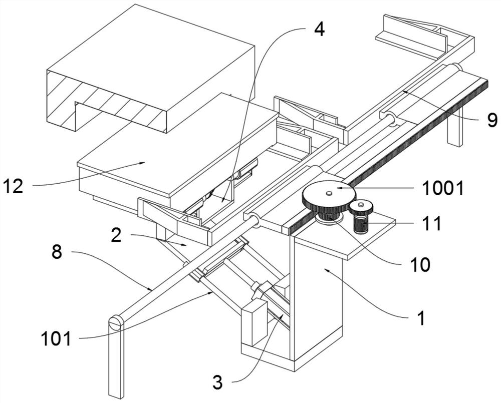
Figure 1 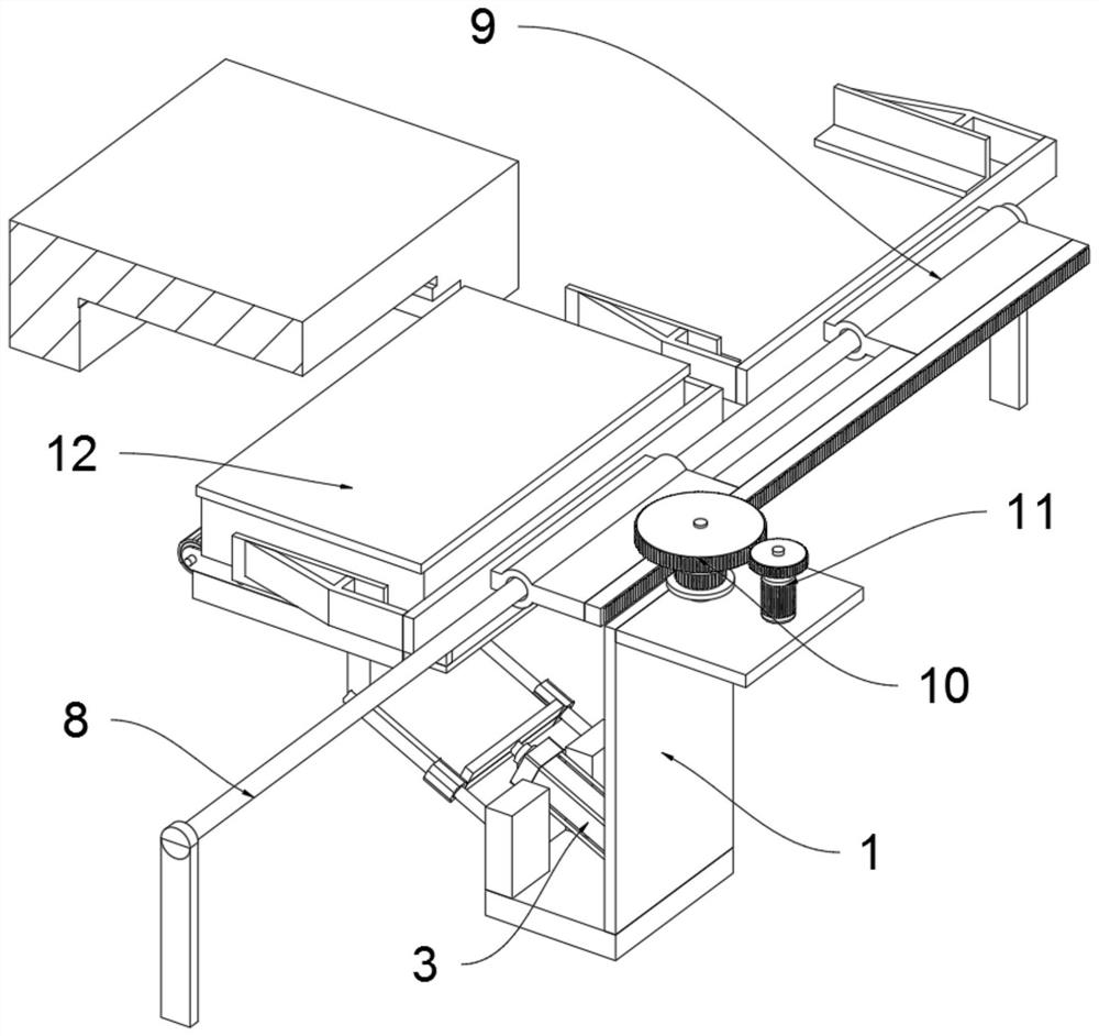
Figure 2 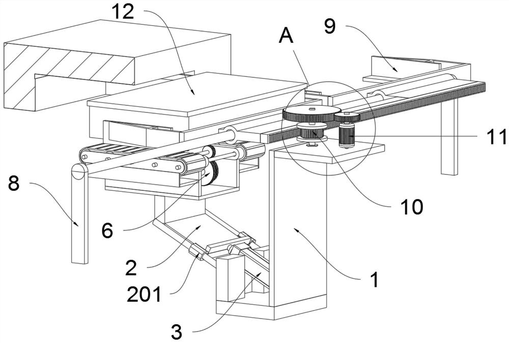
Figure 3
Abstract
Description
Technical field
[0001] The present invention belongs to the field of empty iron battery pack replacement technology, and more particularly to a new energy-free iron power battery pack automatic replacement device.Background technique
[0002] Empty iron, namely hanging air monorail transportation system, different from the subway and trajectors, the orbit of the empty iron is above a rail transit that hangs on the air orbit. New energy empty rails refer to the aerial suspension rail train with lithium battery as traction power, the system adopts new energy, new materials, new design, integrated related mature technology construction. The system has high and comfortable and safe and safe, low energy saving, low-cost, small adaptability, small construction period is small, and the view of the beautiful view of the view is suitable for China's national conditions, and the future China urban and rural and intercoucitation achieves three-dimensional traffic Dock, the central urban transportati...
Examples
Embodiment
[0033]Appendfigure 1 AdherentFigure 8Down:
[0034]The present invention provides a new energy source empty iron power battery pack automatic replacement device including a total bracket 1, a telescopic driving member 3, a bracket 4, a push-pull belt 5, a conversion shaft 6, a driver a 7, a robot 9, a limit drive Wheel 10, driving member two 11, lithium battery pack 12; inner sliding connection with lifting frame 2; the housing of the telescopic driving member 3 is fixed to the total bracket 1, and the output shaft end of the telescopic driving member 3 is fixedly connected The lower end of the lift frame 2; the lower surface of the bracket 4 is connected to the upper end of the lift 2 by welding; the side frame of the pumping conveyor belt 5 is fixed above the bracket 4 by welding; the conversion shaft 6 is transferred to the bracket through the bearing 4 of the groove; the drive member is fixed to the upper side of the bracket 4, and the output shaft of the drive member 7 is engaged ...