
Carbon fiber composite fairing, forming mold and forming method thereof
A composite material and forming mold technology, which is applied in the field of forming molds and their forming, and carbon fiber composite fairings, can solve problems such as the inability to meet the requirements of high performance and light weight in aerospace
Patent Information
- Authority / Receiving Office
- CN · China
- Current Assignee / Owner
- Publication Date
- 2021-05-18
Smart Images
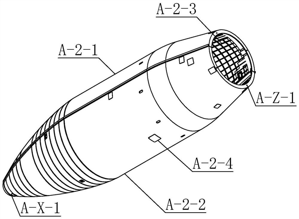
Figure 1 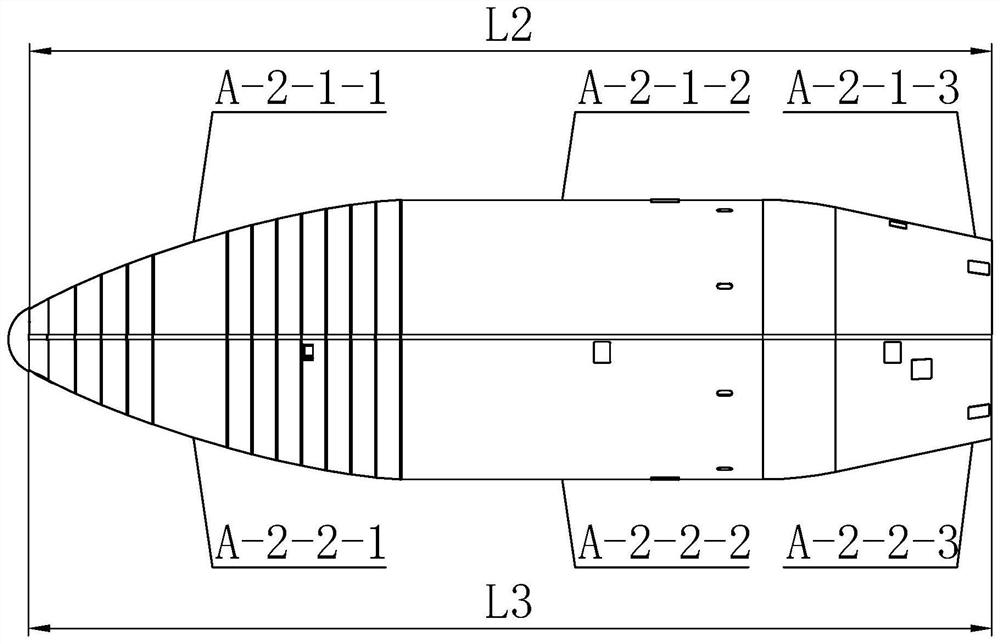
Figure 2 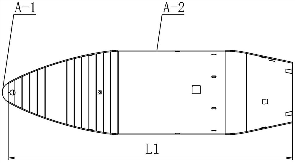
Figure 3
Abstract
Description
technical field
[0001] The invention relates to the technical field of carbon fiber composite material molding, in particular to a carbon fiber composite fairing, a molding die and a molding method thereof. Background technique
[0002] Composite materials are the material basis of high-performance products and an important guarantee for the realization of advanced design concepts and technologies. Due to its lightweight and high-strength structural advantages, high-performance composite materials have been successfully used in many national key fields, and composite fairings are used in rockets. The high-performance and lightweight requirements of aerospace are an important project for the upgrading of my country's rockets. There are many innovation difficulties, large technical spans, and high complexity, representing the highest level of my country's rocket manufacturing. The existing fairings used to match the rocket are made of metal materials, and the structure is com...
Examples
specific Embodiment approach 1
[0066] Specific implementation mode one: combine Figure 1 to Figure 15 Describe this embodiment, a carbon fiber composite material fairing of this embodiment, the carbon fiber composite material fairing includes a terminal cap A-1, a shell A-2 and several connecting pieces, and the shell A-2 is a rotary body structure, the end cap A-1 is installed on the head of the housing A-2 through multiple connecting pieces, and the housing A-2 is cut along the horizontal plane where the shaft is located to form the I quadrant half cover A-2-1 and A-2-1 with the same structure. Ⅲ quadrant half cover A-2-2, Ⅰ quadrant half cover A-2-1 is detachably connected with Ⅲ quadrant half cover A-2-2 through multiple connectors, Ⅰ quadrant half cover A-2-1 and Ⅲ quadrant The inner surface of the half-cover A-2-2 is equipped with reinforcing ribs A-2-3, and the reinforcing ribs A-2-3 are grid-reinforced structures, and the I quadrant half-cover A-2-1 and III quadrant half The outer side of cover A-...
specific Embodiment approach 2
[0067] Specific implementation mode two: combination Figure 1 to Figure 9 Describe this embodiment, the I quadrant half cover A-2-1 of this embodiment includes I quadrant head end A-2-1-1, I quadrant middle section A-2-1-2 and I quadrant tail end A-2- 1-3, Ⅲ quadrant half cover A-2-2 includes Ⅲ quadrant head A-2-2-1, Ⅲ quadrant middle A-2-2-2 and Ⅲ quadrant tail A-2-2-3; Ⅰ The first end of the quadrant A-2-1-1 and the first end of the third quadrant A-2-2-1 are fastened together to form the first end of the shell A-X. The first end of the shell A-X is a conical shell structure. The lower bottom surface of A-X is provided with a first opening, and the upper bottom surface of A-X at the head end of the shell is provided with a small-end inversion flange A-X-1; A-2-1-2 in the middle section of the I quadrant and A-2-2- in the middle section of the III quadrant 2 After fastening, the middle section A-Y of the shell is formed. The middle section A-Y of the shell is a cylindrical ...
specific Embodiment approach 3
[0068] Specific implementation mode three: combination figure 1 To illustrate this embodiment, the outer diameters of the upper and lower bottom surfaces of the middle section A-Y of the housing in this embodiment are both D1, D1=1200mm, the outer diameter of the lower bottom surface of the head end A-X of the housing is equal to the outer diameter of the upper and lower bottom surfaces of the middle section A-Y of the housing, and the housing The outer diameter of the upper bottom surface of the tail end A-Z is D2, D2=850mm, the outer diameter of the lower bottom surface of the tail end A-Z of the shell is equal to the outer diameter of the upper and lower bottom surface of the middle section A-Y of the shell, and the length of the shell A-2 is L1, L1=4125.9 mm. Other compositions and connections are the same as those in Embodiment 1 or Embodiment 2.