
Semi-automatic heat exchange tube welding device
A semi-automatic welding and heat exchange tube technology, which is applied in welding equipment, gas flame welding equipment, cleaning methods using gas flow, etc., can solve the problems of low welding efficiency, improve work efficiency, reduce workload, and improve welding efficiency Effect
Patent Information
- Authority / Receiving Office
- CN · China
- Patent Type
- Applications(China)
- Current Assignee / Owner
- Publication Date
- 2021-07-27
Smart Images
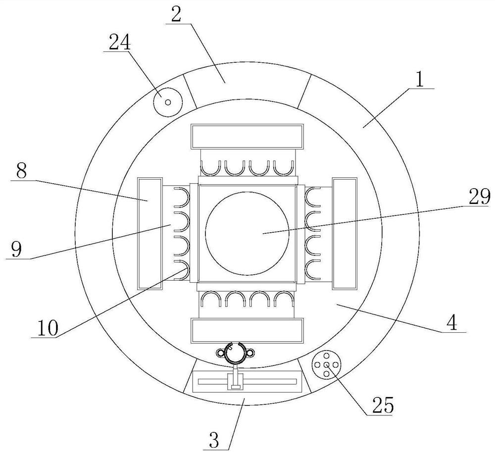
Figure 1 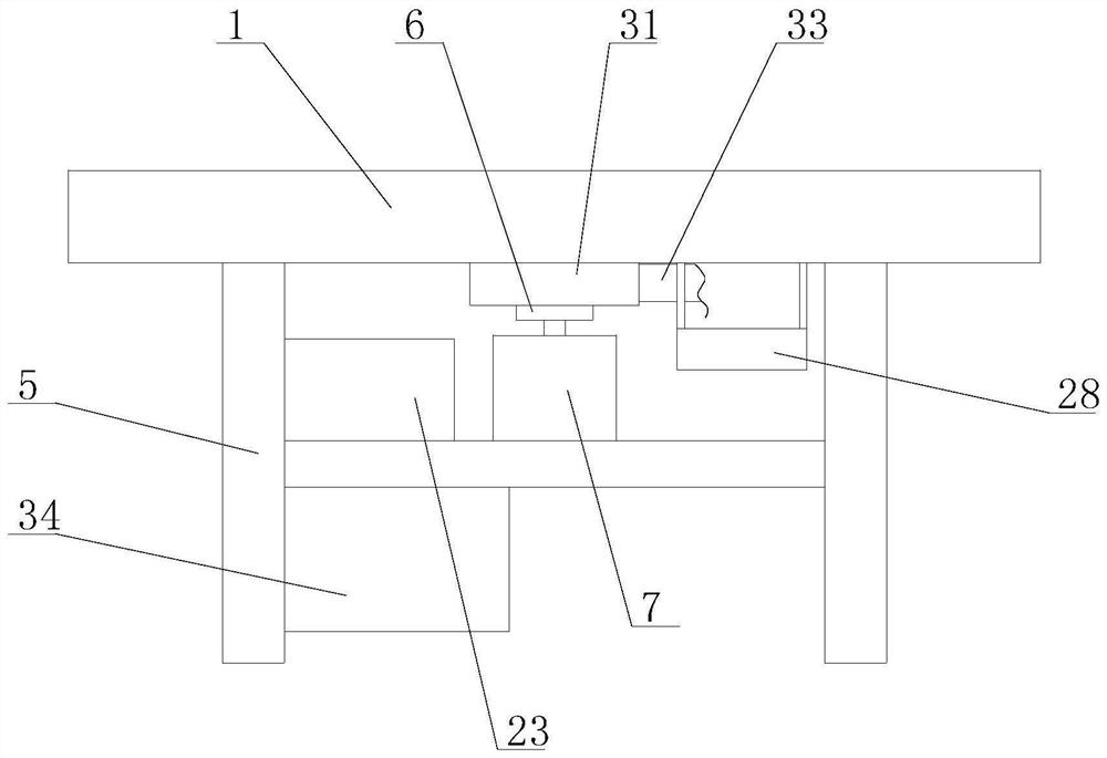
Figure 2 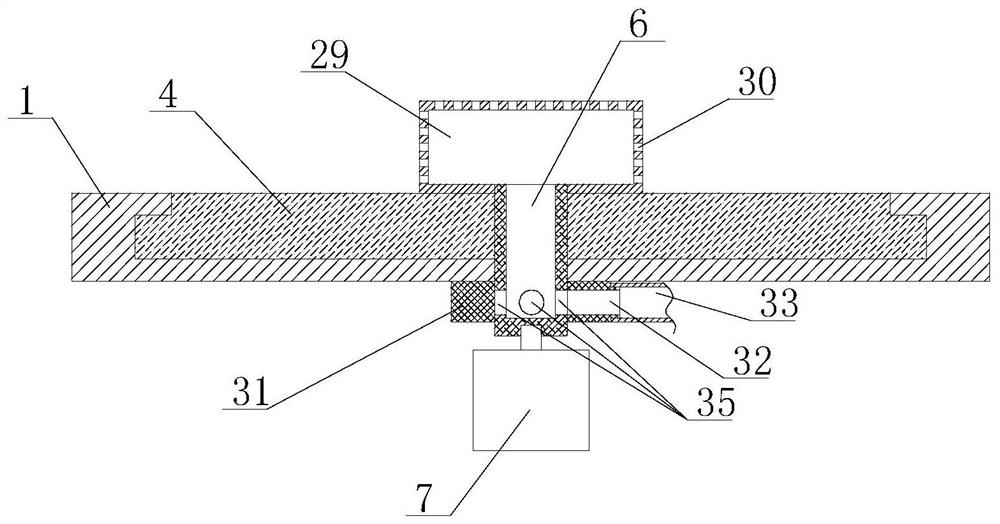
Figure 3
Abstract
Description
technical field
[0001] The invention relates to the technical field of heat exchanger production, in particular to a device for semi-automatically welding heat exchange tubes. Background technique
[0002] A heat exchanger is an energy-saving device that transfers heat between materials between two or more fluids at different temperatures. It transfers heat from a fluid with a higher temperature to a fluid with a lower temperature, so that the fluid temperature reaches the process The specified index is to meet the needs of the process conditions, and it is also one of the important equipment to improve energy utilization; when the heat exchanger is produced, the tail of the heat exchange tube needs to be welded to the tube sheet, and the tube sheet corresponds to the heat exchange tube. The installation groove, each tube plate can weld several heat exchange tubes; at present, the welding method of heat exchange tubes is mainly for workers to hold flame spray guns for weldin...
Examples
Embodiment Construction
[0033] The following will clearly and completely describe the technical solutions in the embodiments of the present invention with reference to the accompanying drawings in the embodiments of the present invention. Obviously, the described embodiments are only some, not all, embodiments of the present invention. The accompanying drawings are for illustrative purposes only, and represent only schematic diagrams, rather than actual drawings, and should not be construed as limitations on this patent. In order to better illustrate the specific implementation of the present invention, some parts of the accompanying drawings will be omitted or enlarged Or reduced, does not represent the size of the actual product. For those skilled in the art, it is understandable that some known structures, components and their descriptions in the drawings may be omitted. Based on the embodiments of the present invention, those of ordinary skill in the art All other embodiments obtained under the pr...