
Multifunctional unmanned aerial vehicle remote sensing device for engineering surveying and use method
A technology of engineering measurement and machine remote sensing, which is applied in the direction of aircraft indicating devices, camera devices, unmanned aircraft, etc., and can solve the problems of remote sensor position adjustment affecting measurement results, inconvenient operation methods, and lack of measurement stability. , to achieve the effect of ensuring the effect of remote sensing measurement, ensuring the stability of descent or lift-off, and ensuring the safety
Patent Information
- Authority / Receiving Office
- CN · China
- Patent Type
- Applications(China)
- Current Assignee / Owner
- Publication Date
- 2021-12-28
Smart Images
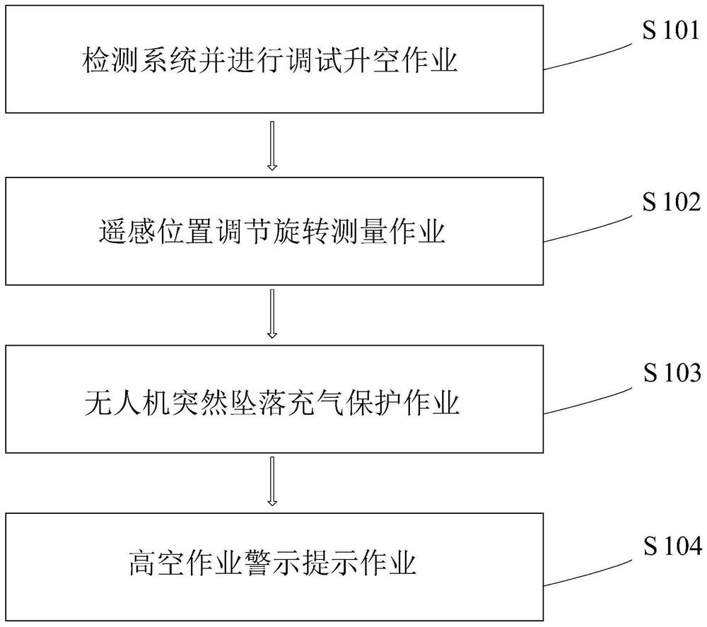
Figure 1 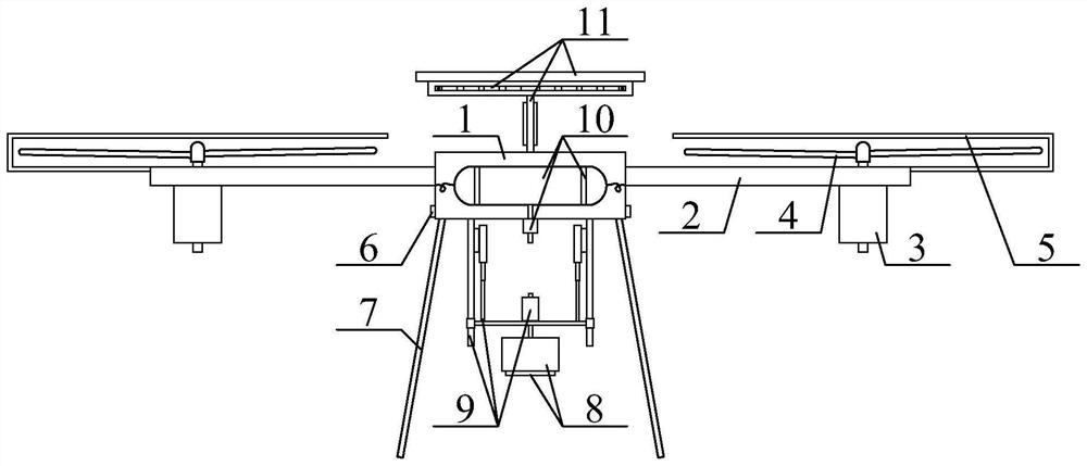
Figure 2 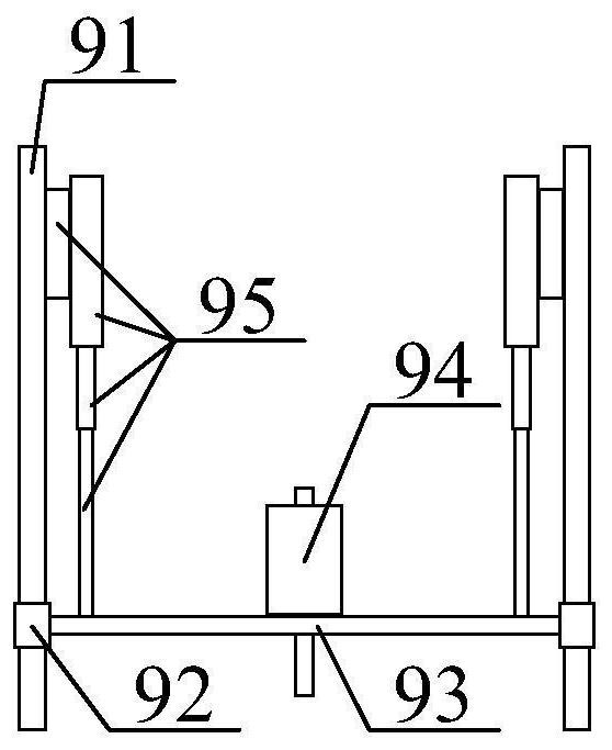
Figure 3
Abstract
Description
technical field
[0001] The invention belongs to the technical field of engineering survey, and in particular relates to a multifunctional remote sensing device for engineering survey and a method for using it. Background technique
[0002] Engineering survey (engineering survey) refers to the general term for all surveying and mapping work in engineering construction, including various surveying work carried out in the stages of engineering construction survey, design, construction and management; in engineering survey, the most used surveying and mapping devices are fixed The fixed position of the frame is measured by the measuring instrument, and the precise measurement and mapping work can be carried out by cooperating with the scale structure. With the development of technology, there is also a certain demand for engineering measurement and mapping devices.
[0003] At present, UAV remote sensing devices for engineering surveys are widely used in engineering surveys. ...
Examples
Embodiment Construction
[0026] The present invention will be further described below in conjunction with accompanying drawing:
[0027] In the picture:
[0028] as attached figure 2 to attach image 3 shown
[0029] A multifunctional UAV remote sensing device for engineering survey, including UAV body 1, wing 2, motor 3, propeller 4, protective cover 5, speed sensor 6, support leg 7, remote sensor 8, rotary adjustable The remote sensing detection rod structure 9, the UAV fall protection airbag structure 10 and the high-altitude operation warning board structure 11, the upper and outer four corners of the UAV body 1 are bolted to the wing 2; the lower and outer sides of the wing 2 are bolted There is a motor 3; the upper end of the output shaft of the motor 3 is keyed to a propeller 4; the outer cover of the propeller 4 is connected with a protective cover 5; the protective cover 5 is connected to the outer end of the wing 2 by bolts; The outer four corners of the lower part of the drone body 1 a...