
Camera shooting system
A camera system and image-side technology, applied in the field of camera systems, can solve problems such as complex shooting environment, imaging limitations, and difficulty in obtaining clear images, and achieve the effects of improving shooting effects, reducing aberrations, and increasing the clear aperture
Patent Information
- Authority / Receiving Office
- CN · China
- Patent Type
- Applications(China)
- Current Assignee / Owner
- Publication Date
- 2022-01-11
Smart Images
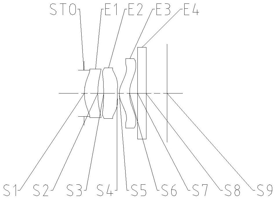
Figure 1 
Figure 2 
Figure 3
Abstract
Description
technical field
[0001] The invention belongs to the field of optical imaging, in particular to a camera system including three lenses. Background technique
[0002] In recent years, consumers have higher and higher requirements for mobile phone shooting functions, and functional requirements such as face recognition and distance measurement have emerged as the times require. However, due to the complexity of the shooting environment, it is difficult to obtain clear images in dim environments. At present, The mobile phone lens is limited in imaging the environment with insufficient light, and cannot achieve a very clear imaging effect. At this time, the infrared lens can solve this problem very well. The infrared lens can enhance the light input of the entire imaging system by collecting infrared light in the shooting environment. Compared with the multiple shooting algorithm synthesis of the night scene mode of the mobile phone lens in the past, the image resolution obtained...
Examples
specific Embodiment 1
[0073] figure 1 It is a schematic diagram of the structure of the lens group in Embodiment 1 of the imaging system of the present invention. The imaging system includes in sequence from the object side to the image side along the optical axis: a diaphragm STO, a first lens E1, a second lens E2, a third lens E3, a filter Slice E4 and imaging surface S9.
[0074] The first lens E1 has positive refractive power, its object side S1 is convex, and its image side S2 is concave. The second lens E2 has negative refractive power, its object side S3 is concave, and its image side S4 is concave. The third lens E3 has positive refractive power, its object side S5 is convex, and its image side S6 is concave. The filter E4 has an object side S7 and an image side S8. The light from the object passes through each of the surfaces S1 to S8 in sequence and is finally imaged on the imaging plane S9.
[0075] As shown in Table 1, it is a table of basic parameters of the camera system in Embodi...
Embodiment 1
[0081] The camera system in embodiment 1 satisfies:
[0082] f×tan(semi-fov)=1.22; wherein, f is the effective focal length of the camera system, and semi-fov is half of the maximum field of view of the camera system.
[0083] DT12 / ImgH=0.49; wherein, DT12 is the effective semi-diameter of the image side of the first lens, and Imgh is half of the diagonal length of the effective pixel area on the imaging surface.
[0084]f23 / f=1.28; wherein, f23 is the combined focal length of the second lens and the third lens, and f is the effective focal length of the camera system.
[0085] f1 / f=2.56; wherein, f1 is the effective focal length of the first lens, and f is the effective focal length of the camera system.
[0086] EPD / f3=1.38; wherein, EPD is the entrance pupil diameter of the camera system, and f3 is the effective focal length of the third lens.
[0087] ET2 / CT2=0.63; wherein, ET2 is the edge thickness of the second lens, and CT2 is the center thickness of the second lens o...
specific Embodiment 2
[0097] image 3 It is a schematic diagram of the lens group structure of Embodiment 2 of the camera system of the present invention. The camera system includes in sequence from the object side to the image side along the optical axis: a diaphragm STO, a first lens E1, a second lens E2, a third lens E3, a filter Slice E4 and imaging surface S9.
[0098] The first lens E1 has positive refractive power, its object side S1 is convex, and its image side S2 is concave. The second lens E2 has negative refractive power, its object side S3 is concave, and its image side S4 is concave. The third lens E3 has positive refractive power, its object side S5 is convex, and its image side S6 is concave. The filter E4 has an object side S7 and an image side S8. The light from the object passes through each of the surfaces S1 to S8 in sequence and is finally imaged on the imaging plane S9.
[0099] As shown in Table 4, it is a table of basic parameters of the camera system of Embodiment 2, w...