
A hidden transmission locking device for doors and windows
A locking device and hidden technology, applied in the field of doors and windows, can solve the problems of exposed locking handle, poor appearance, difficult to operate, etc., achieve the effect of beautiful appearance, stable operation, and improve the level of intelligence
Patent Information
- Authority / Receiving Office
- CN · China
- Patent Type
- Patents(China)
- Current Assignee / Owner
- Publication Date
- 2022-03-25
Smart Images
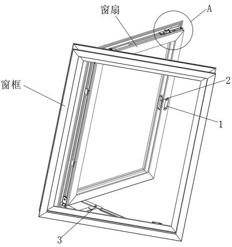
Figure 1 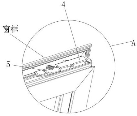
Figure 2 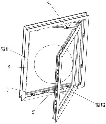
Figure 3
Abstract
Description
technical field
[0001] The invention relates to the field of doors and windows, in particular to a hidden transmission locking device for doors and windows. Background technique
[0002] In the prior art, the door and window structure generally includes: a window sash, the frame of which is embedded with glass; a window frame, which is installed on the outside of the window sash, between the upper end of the left part A friction hinge is installed between the upper end of the right part frame of the window sash and another friction hinge is installed between the upper end of the right part frame of the window frame; the handle is installed on the window frame and can be used to operate the opening and locking of doors and windows The latch device, which is installed between the sash and the window frame, is used to lock the doors and windows; the slide piece, which connects the handle and the latch device, slides with the rotation of the handle, thereby driving the latch dev...
Examples
Embodiment 1
[0041] see Figure 1-10 , a hidden transmission locking device for doors and windows, including a locking device 2 installed in the middle of the side of the window sash, the locking device 2 includes an upper cover 21 and a lower cover 22 that fit together, and the lower cover 22 passes through the The rotating shaft is connected with an eccentric wheel 26 and a driving gear 27, the eccentric wheel 26 is fixed with a driven gear 261 meshing with the driving gear 27, a force arm 271 is fixed on one side of the driving gear 27, and a rubidium magnet is fixed on one side of the force arm 271 272, an electromagnet 24 corresponding to the rubidium magnet 272 is fixed in the lower cover plate 22, two sliders 23 are slidably connected between the upper cover plate 21 and the lower cover plate 22, and the two sliders 23 are arranged symmetrically. A flexible steel belt 25 is fixed between the opposite sides of the block 23, and the flexible steel belt 25 is sleeved on the eccentric w...