
Sectional material component, sectional material and photovoltaic module frame
A technology for photovoltaic modules and profiles, applied in the fields of profiles, photovoltaic module frames, and profile components, can solve the problems of increasing the failure rate of modules, difficult to form convection, and accelerate the aging of components, so as to reduce the cost of raw materials and processing costs, good air convection and The effect of cycle, prolonging working life
Patent Information
- Authority / Receiving Office
- CN · China
- Patent Type
- Applications(China)
- Current Assignee / Owner
- Publication Date
- 2022-03-11
- Estimated Expiration
- Not applicable · inactive patent
Smart Images
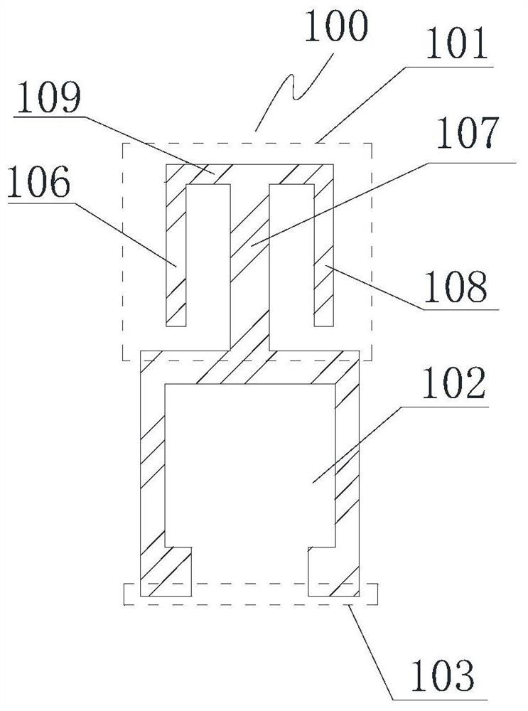
Figure 1 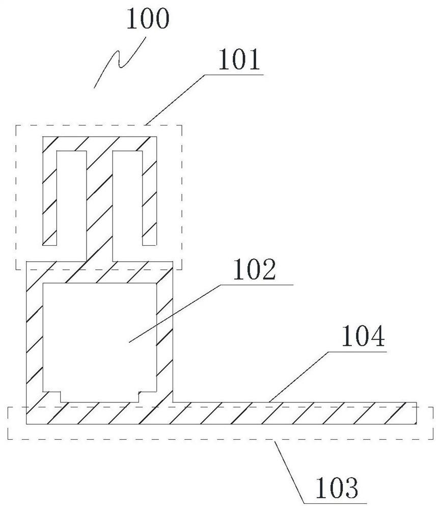
Figure 2 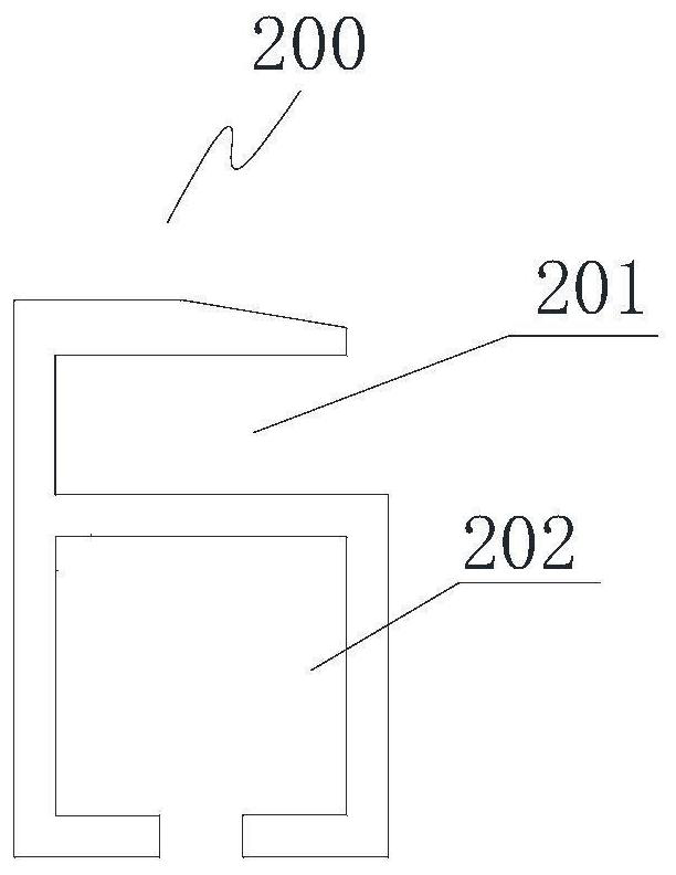
Figure 3
Abstract
Description
technical field
[0001] The invention relates to a profile component, a profile and a frame of a photovoltaic module. Background technique
[0002] A profile is an object with a certain geometric shape made of a material with certain strength and toughness through rolling, extrusion, casting and other processes. Due to the limitation of the manufacturing process, the cross-sectional shape of a profile is generally fixed, and its shape and thickness are uniform on each cross-section in the length direction. When selecting profiles, generally according to actual installation requirements, select profiles that match in terms of shape, material, and mechanical properties. However, in the actual application scene after installation, different positions of the profile bear different external forces, which leads to deformation or even tearing at some positions of the profile. In order to avoid such deformation or tearing, the existing Generally, the technology adopts a design that...
Examples
Embodiment 1
[0073] This embodiment provides a profile member 100, the profile member 100 is installed on the profile body 200 to form a profile 300; the profile component constitutes at least a part of the profile cavity. Preferably, the profile component 100 also forms the profile base 103 .
[0074] The profile body 200 has a bearing part for carrying the workpiece to be installed. In some specific embodiments, the bearing part is a notch 201, and the workpiece to be installed is installed in the notch; in other specific embodiments, the bearing The portion can also be in other shapes, such as a flat plate, and is not limited to the shape of the notch. The profile body 200 may also include a cavity for supporting the load-bearing portion, which is named as the first cavity 202 here.
[0075] Figure 1a A profile member 100 with a specific structure is shown. As shown in the figure, the profile member 100 has a connecting portion 101 connected to the profile body 200, and a second cavi...
Embodiment 2
[0085] Such as figure 2 As shown, this embodiment provides a profile member 100, and Figure 1b The difference between the profile members shown is that there are two second cavities 102, named here as the upper second cavity 102a and the lower second cavity 102b, and the two second cavities are located below the first cavity , not embedded in the second cavity. Two second die cavities are arranged horizontally, and the two second die cavities arranged horizontally are parallel to each other. The so-called "horizontally arranged" here means that the dimension on the width of the second cavity is larger than the dimension on its height
[0086] The profile member 100 is combined with the profile body 200 to form a corresponding profile. In this embodiment, the bottom edge of the lower second cavity 102b constitutes the bottom edge 103 of the profile. The bottom edge of the profile is the contact surface with the installation station.
Embodiment 3
[0088] Such as Figure 3a As shown, this embodiment provides a profile member 100, and Figure 1a The difference between the profile members shown is that: the profile member 100 is not embedded in the first cavity 202, and the profile component 100 is connected to the bottom edge of the first cavity 202 through the top edge of the second cavity 102. The specific connection method Can be glued or fastener connected.
[0089] Such as Figure 3b As shown, this embodiment provides a profile member 100, and Figure 1b The difference between the profile members shown is that: the profile member 100 is not embedded in the first cavity 202, and the profile component 100 is connected to the bottom edge of the first cavity 202 through the top edge of the second cavity 102. The specific connection method Can be glued or fastener connected.
[0090] As a modification, the profile body may not have a cavity, and the cavity of the profile is formed by the second cavity on the profile m...