
Inner container pulling and riveting structure, manufacturing method thereof and steaming and baking machine
A manufacturing method and pull riveting technology, applied in the direction of connecting components, rivets, mechanical equipment, etc., can solve problems such as steam leakage, cracks, whitening, etc., and achieve the effect of convenient sealing
Patent Information
- Authority / Receiving Office
- CN · China
- Patent Type
- Applications(China)
- Current Assignee / Owner
- Publication Date
- 2022-03-22
Smart Images
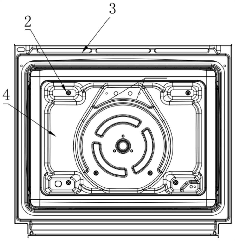
Figure 1 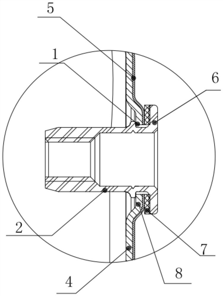
Figure 2 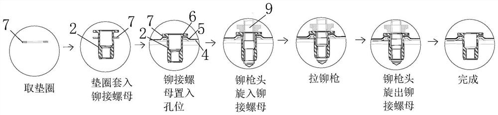
Figure 3
Abstract
Description
technical field
[0001] The invention relates to the technical field of home appliances, in particular to a riveting structure of an inner container, a manufacturing method thereof, and a steaming and roasting machine. Background technique
[0002] At present, the inner tank of household appliances (such as ovens, steamers, or integrated steaming and baking machines) usually uses riveting to fix the riveting nuts, relying on the screw rod on the special riveting gun for riveting nuts to rotate and pull the riveting nuts, so that the riveting nuts undergo longitudinal compression. The thin-walled area at the end is convexly deformed, and the inner tank plate is clamped, thereby realizing the riveting process. Then, use screws to firmly connect other components on the outside of the liner (such as heating pipes, fans, lampshades, brackets, etc.) to the riveting nuts. At present, after the inner tank of the steam-baking machine is enamelled, the moment the rivets are tightened ...
Examples
Embodiment 1
[0040] The inner tank riveting structure disclosed in this embodiment, Figure 1-Figure 2 As shown, it includes a hole 1 and a riveting nut 2, the hole 1 runs through the substrate and the enamel layer 5 of the inner container 4 of the household appliance 3, the riveting nut 2 is embedded in the hole 1, that is, the riveting nut 2 is stable It is fixed inside the hole 1 so that the riveting nut 2 is arranged on the enamel layer 5 of the inner liner 4 . figure 2 As shown, the opening of the rivet nut 2 is turned outward to form a retaining edge 6, figure 2 As shown, the retaining edge 6 presses against the opening periphery of the hole 1 , and the opening periphery is the enamel layer 5 , that is, the retaining edge 6 presses against the enamel layer 5 at the opening periphery of the hole 1 . A washer 7 is sandwiched between the opening periphery of the hole 1 and the retaining edge 6, the washer 7 is set on the riveting nut 2, and the inner ring wall of the washer 7 seals t...
Embodiment 2
[0050] The difference between this embodiment and Embodiment 1 is that the surface of the enamel layer 5 protrudes outward by 1.1mm to form the boss 8, the thickness of the gasket 7 is 0.6mm, and the silicone gasket 7 is resistant to Temperature above 225°C, the Shore hardness of the silicone gasket 7 is 65°C, and the distance across the sides of the regular hexagon at the hole position 1 is preferably set to 7mm. Other components and principles of this embodiment are the same as those of Embodiment 1, and will not be repeated here.
Embodiment 3
[0052] The difference between this embodiment and Embodiment 1 is that the surface of the enamel layer 5 protrudes outward by 1mm to form the boss 8, the thickness of the gasket 7 is 0.5mm, and the silicone gasket 7 is temperature-resistant. Above 225°C, the Shore hardness of the silicone gasket 7 is 60°C, and the distance across the sides of the regular hexagon at the hole position 1 is preferably set to 6.5mm. Other components and principles of this embodiment are the same as those of Embodiment 1, and will not be repeated here.