
Plug nozzle engine with secondary flow injection structure
A plug-type nozzle and secondary flow technology, which is applied in the direction of machines/engines, rocket engine devices, mechanical equipment, etc., can solve the problem of not being suitable for using plug-type nozzles, etc. The effect of the amount of medicine and the increase of the range
Patent Information
- Authority / Receiving Office
- CN · China
- Patent Type
- Applications(China)
- Current Assignee / Owner
- Publication Date
- 2022-07-22
Smart Images
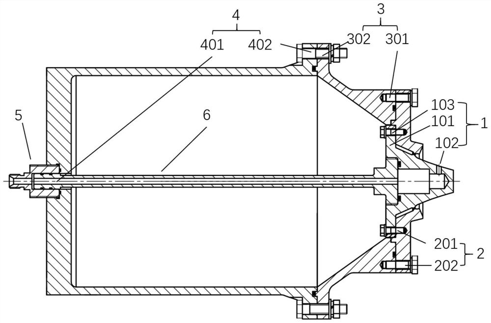
Figure 1 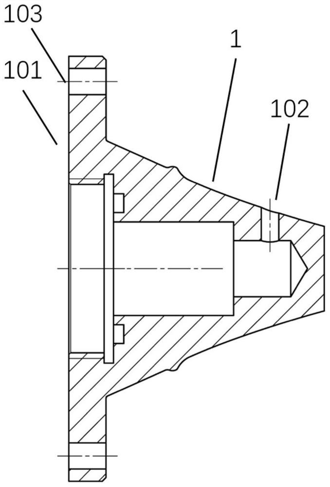
Figure 2 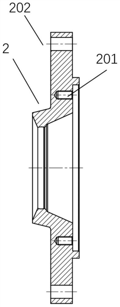
Figure 3
Abstract
Description
technical field
[0001] The invention relates to a plug nozzle engine with a secondary flow injection mode, belonging to the field of aerospace engines. Background technique
[0002] With the development of solid rocket motors, it is difficult to improve the performance of traditional bell-shaped nozzles, and they are over-expanded at low altitudes and under-expanded at high altitudes. There is a large performance loss at most of the height of the nozzle. The plug nozzle automatically adjusts and expands with the change of the external atmospheric pressure, so that the gas is in a fully expanded state at different heights. Such height compensation characteristics make the performance of the plug nozzle far better than that of the clock outside the design point. shaped nozzle.
[0003] The use of the plug nozzle on the aerospace engine needs to meet the vector control requirements of the aircraft and provide the aircraft with a certain pitch and yaw channel control capabilit...
Examples
Embodiment
[0038] like figure 1 As shown, a plug nozzle engine with a secondary flow injection structure disclosed in this embodiment consists of a plug cone 1, an annular cover 2, a front end 3 of the combustion chamber, a rear end 4 of the combustion chamber, a connector 5 and two The secondary flow guide rod 6 is formed.
[0039] like figure 2As shown, the plug cone 1 includes a rib column 101 , a plug cone hole 102 and a rib column opening 103 .
[0040] like image 3 As shown, the annular cover 2 includes a threaded hole 201 and a through hole 202 .
[0041] like Figure 4 As shown, the front end 3 of the combustion chamber includes a threaded opening 301 and a through hole 302 .
[0042] like Figure 5 As shown, the rear end 4 of the combustion chamber includes a bottom opening 401 and a through hole 402 .
[0043] Use 4 studs to pass through the openings 103 of the 4 rib columns 101 of the plug cone respectively, and fix them on the annular cover 2 through the threaded hol...