
Vacuum suction pad and substrate holder
a vacuum suction pad and substrate technology, applied in mechanical devices, abrasive surface conditioning devices, manufacturing tools, etc., can solve problems such as inability to achieve the effect, and achieve the effects of preventing substrate separation, reducing the amount of upward warping of the substrate, and increasing the suction for
Patent Information
- Authority / Receiving Office
- US · United States
- Patent Type
- Patents(United States)
- Current Assignee / Owner
- Publication Date
- 2020-05-05
Smart Images
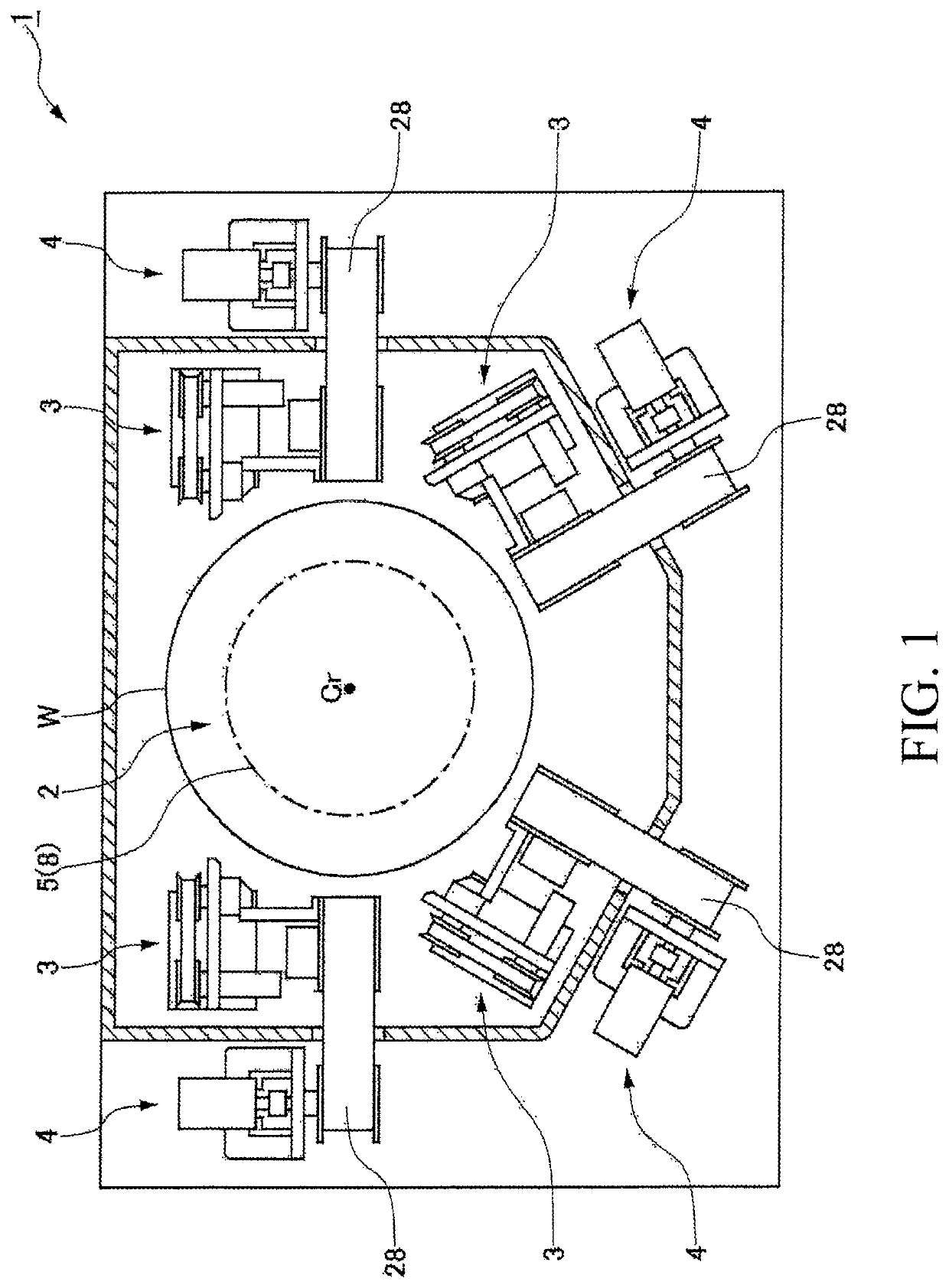
Figure 1 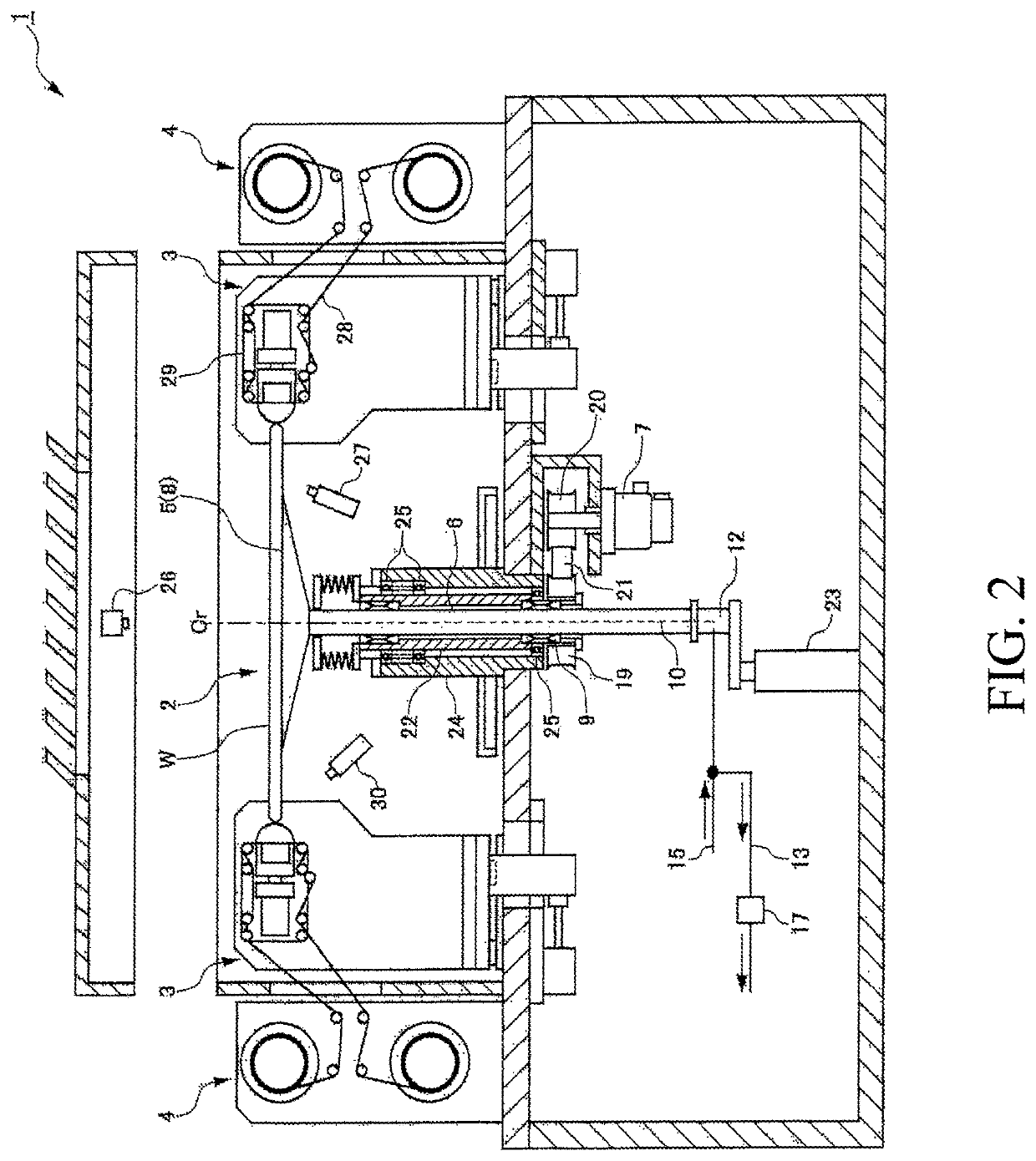
Figure 2 
Figure 3
Abstract
Description
CROSS-REFERENCE TO RELATED APPLICATION
[0001] This application is based upon and claims benefit of priority from Japanese Patent Application No. 2017-070755 filed on Mar. 31, 2017, the entire contents of which are incorporated herein by reference.BACKGROUND OF THE INVENTIONField of the Invention
[0002] The present invention relates to a vacuum suction pad to be adhered to a stage of a substrate holder.Description of the Related Art
[0003] A vacuum suction pad is adhered to a stage of a substrate holder and is used for holding a substrate on the stage by vacuum suction (see, for example, Japanese Patent Laid-Open No. 2010-153585). A plurality of closed sections (vacuum suction areas) surrounded by convexities are formed on a suction surface (top surface) of a conventional vacuum suction pad. Each of the plurality of closed sections is provided with an intake / exhaust port, and a plurality of the intake / exhaust ports are connected to intake / exhaust lines that can independently take in and ex...
Examples
first embodiment
[0046]First, the configuration of a substrate holder according to an embodiment of the present invention will be described with reference to the drawings. FIG. 1 is a plan view of a polishing apparatus including the substrate holder of this embodiment, and FIG. 2 is a cross-sectional view of the polishing apparatus including the substrate holder of this embodiment. As illustrated in FIG. 1 and FIG. 2, a substrate holder 2 for holding horizontally a substrate W, which is an object to be polished, is mounted in the central portion of a polishing apparatus 1. Four polishing head mechanisms 3 are disposed around the substrate W held by the substrate holder 2, and a polishing tape supply and collection mechanism 4 is provided on the outside, in a radial direction, of each of the polishing head mechanisms 3.
[0047]The substrate holder 2 includes a stage 5 for placing a substrate W thereon, a rotating shaft 6 connected to the central portion of the stage 5, and a motor 7 for rotating the ro...
second embodiment
[0084]Next, the configuration of a substrate holder according to the second embodiment of the present invention will be described with reference to the drawings. FIG. 18 is a cross-sectional view of a polishing apparatus including the substrate holder of this embodiment. As illustrated in FIG. 18, a first tube 10 and a second tube 11 are inserted through the inside of a rotating shaft 6 of a substrate holder 2. The first tube 10 and the second tube 11 are connected to a first vacuum line 13 and a second vacuum line 14, which are vacuum sources, respectively, through a rotary joint 12 attached to the lower end of the rotating shaft 6. The first tube 10 and the second tube 11 are also connected a first nitrogen gas supply line 15 and a second nitrogen gas supply line 16 which are fluid supply sources for releasing a substrate W from a vacuum suction pad 8 after a process.
[0085]A first vacuum regulator 17 and a second vacuum regulator 18 are attached to the first vacuum line 13 and the...