

Image forming apparatus
a technology of forming apparatus and forming chamber, which is applied in the direction of electrographic process apparatus, instruments, corona discharge, etc., can solve the problems of non-image parts, unable to obtain clear color images, and unable to uniformly charge toner, so as to improve the transfer efficiency, reduce the amount of fog, and improve the effect of transfer efficiency
Patent Information
- Authority / Receiving Office
- US · United States
- Patent Type
- Applications(United States)
- Current Assignee / Owner
- Publication Date
- 2005-04-21
- Estimated Expiration
- Not applicable · inactive patent
Smart Images
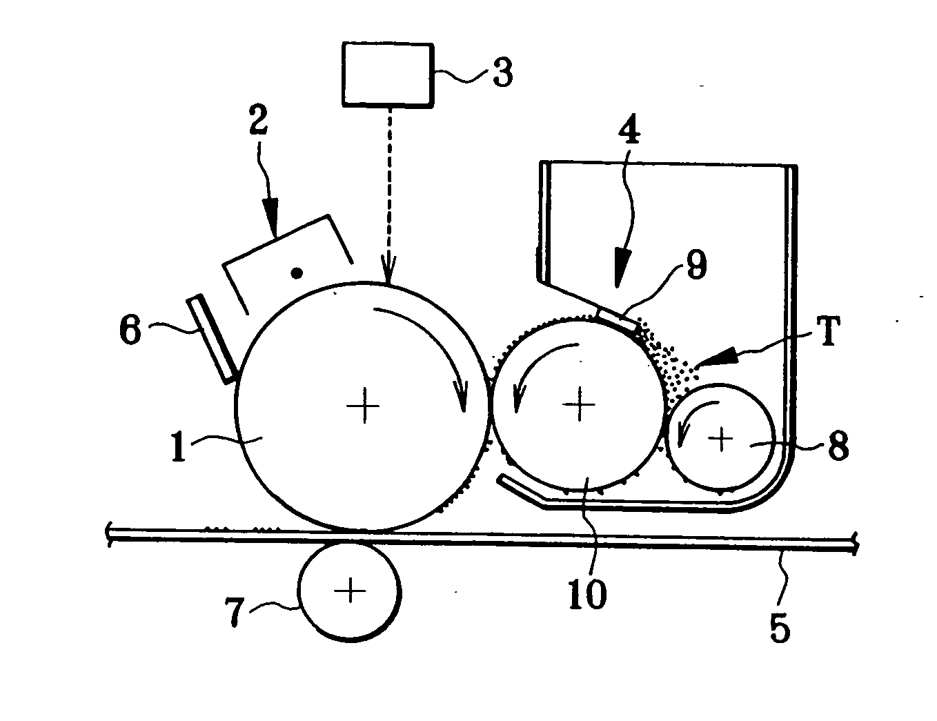
Figure 1 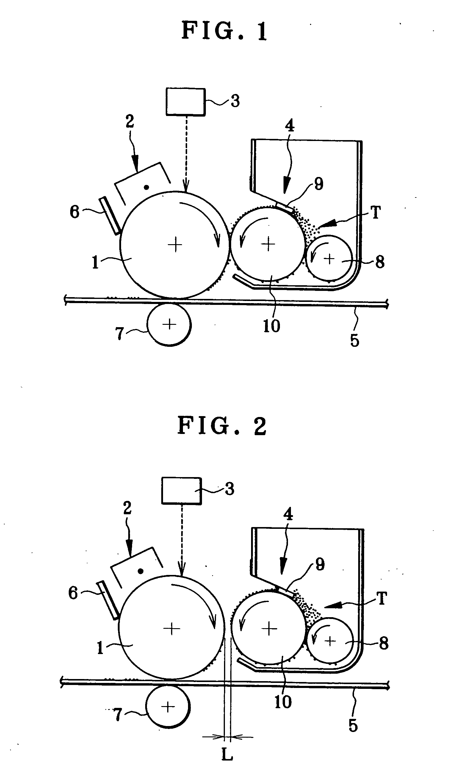
Figure 2 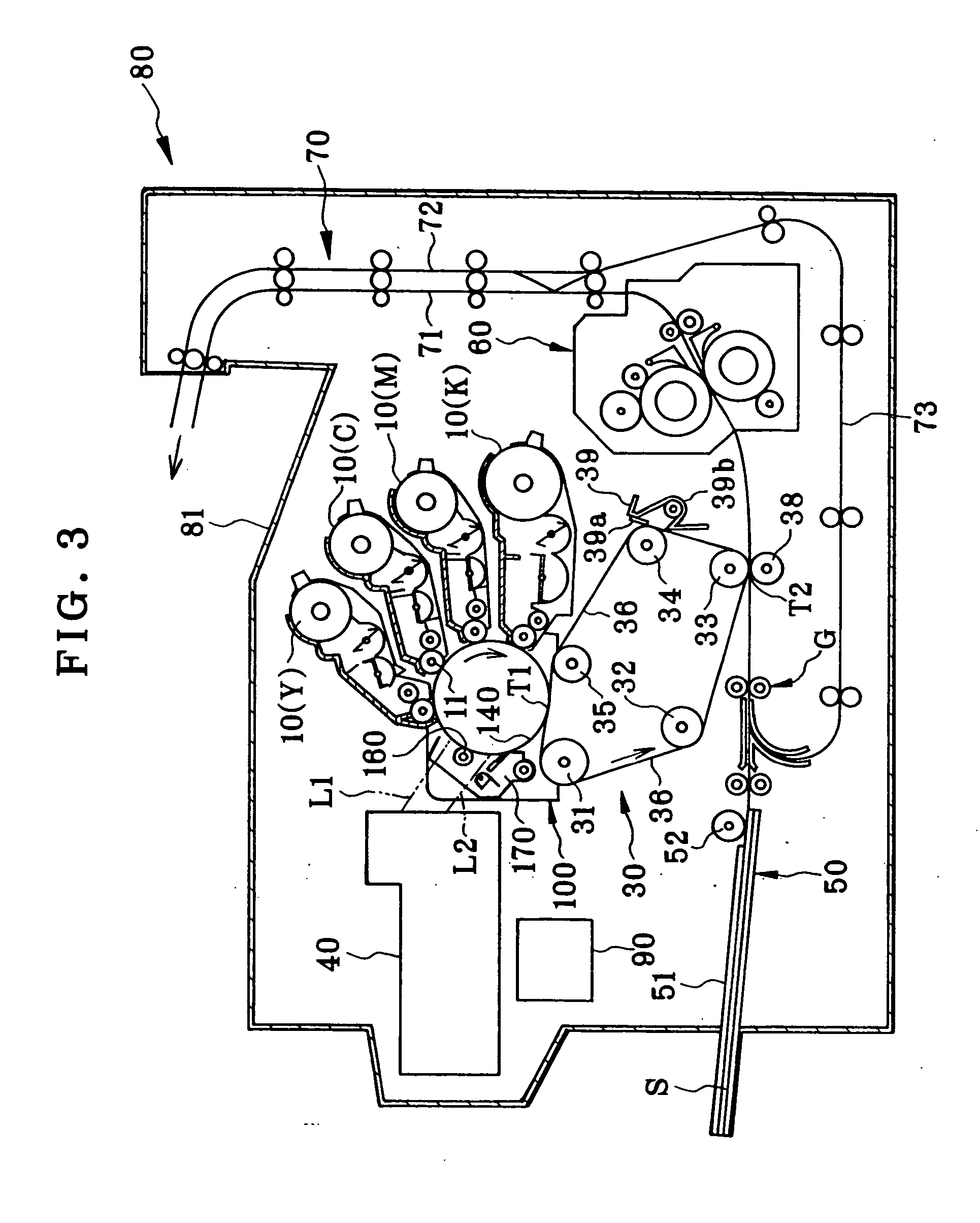
Figure 3
Abstract
Description
BACKGROUND OF THE INVENTION
[0001] The present invention relates to an image forming apparatus employing electrophotographic technology and particularly to an image forming apparatus which transfers a visible toner image formed on a latent image carrier to a recording medium electrostatially.
[0002] In a conventional image forming apparatus, a photoreceptor as a latent image carrier such as a photosensitive drum or a photosensitive belt is rotatably supported to the main body of the image forming apparatus. During the image forming operation, a latent image is formed onto a photosensitive layer of the photoreceptor and, after that, is developed with toner particles to form a visible image. Then, the visible image is transferred to a recording medium. For transferring the visible image, there are a method of directly transferring the visible image to the recording medium by using a corona discharge or a transferring roller, and a method of transferring the visible image to the record...
Examples
example 1
[0202] The toner (1), the toner (4), and the organic photoreceptors [OPC (1), OPC (4), OPC (5)] obtained above were employed to have combinations as shown in Table 1 and adopted to the apparatus of contact single-component developing method shown in FIG. 1.
[0203] For tests, the peripheral velocity of the organic photoreceptor was set to 180 mm / s. The development roller (1) obtained above was employed and the peripheral velocity thereof was set to have a specific ratio of 2 relative to the organic photoreceptor. The development roller was pressed against the organic photoreceptor at pressing load 40 gf / cm with a nip width of 1.5 mm.
[0204] A toner regulating blade was made by bending the end of a SUS plate of 80 μm in thickness by 10° to have projection length of 0.6 mm. The work function was 5.01 eV. The toner regulating blade was arranged to be pressed against the development roller with a linear load of 33 gf / cm in such a manner as to make the toner layer on the development rolle...
example 2
[0215] The toner (1), the toner (4), and the organic photoreceptors [OPC (1), OPC (4), OPC (5)] obtained above were employed to have combinations as shown in Table 2 and adopted to the apparatus of non-contact single-component developing method shown in FIG. 2.
[0216] For tests, the peripheral velocity of the organic photoreceptor was set to 180 mm / s. The development roller (1) was employed and the peripheral velocity thereof was set to have a specific ratio of 2 relative to the organic photoreceptor. A development gap L was set to 210 μm (the space was adjusted by a gap roller). A developing bias was applied under condition that an alternating current (AC) to be superimposed on a direct current (DC) of −200 V was set to have a frequency of 2.5 kHz, and P-P voltage was set to 1500 V.
[0217] Similarly to Example 1, a regulating blade- made of a SUS plate of 80 μm in thickness was used as the toner regulating blade. The toner regulating blade was arranged to be pressed against the dev...
example 3
[0222] The toners for four colors: the cyan toner (1); the magenta toner (4); the yellow toner (5); and the black toner (6), and the organic photoreceptor [OPC (4)] obtained above were combined to form full-color images. As an image forming apparatus, a four-cycle color printer of the non-contact developing type as shown in FIG. 3 (in this case, however, the aluminium pipe of the organic photoreceptor [OPC (4)] was 85.5 mm in diameter) was assembled. In addition, a tandem color printer of the contact developing type as shown in FIG. 4 (in this case, however, the aluminium pipe of the organic photoreceptor [OPC (4)] was 40 mm in diameter) was assembled.
[0223] Either printer can provide uniform fullcolor images. After character image corresponding to color original containing 5% each color was continuously printed on 10000 sheets of paper, the total amount of four color toners collected by cleaning the photoreceptor was measured. In case of the four cycle type color printer shown in ...