
Device for supplying secondary air in a gas turbine engine
a gas turbine engine and secondary air technology, applied in the direction of engines, efficient propulsion technologies, mechanical devices, etc., can solve the problems of reducing the overall efficiency of the engine, preventing adequate cooling, wasting useful energy, etc., and achieve the effect of increasing temperature and pressur
Patent Information
- Authority / Receiving Office
- US · United States
- Patent Type
- Applications(United States)
- Current Assignee / Owner
- Publication Date
- 2005-06-23
Smart Images
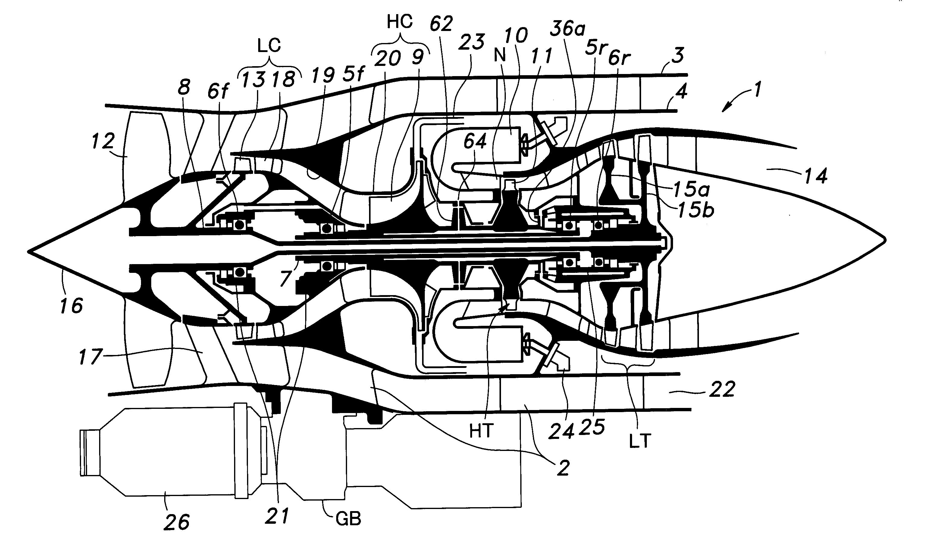
Figure 1 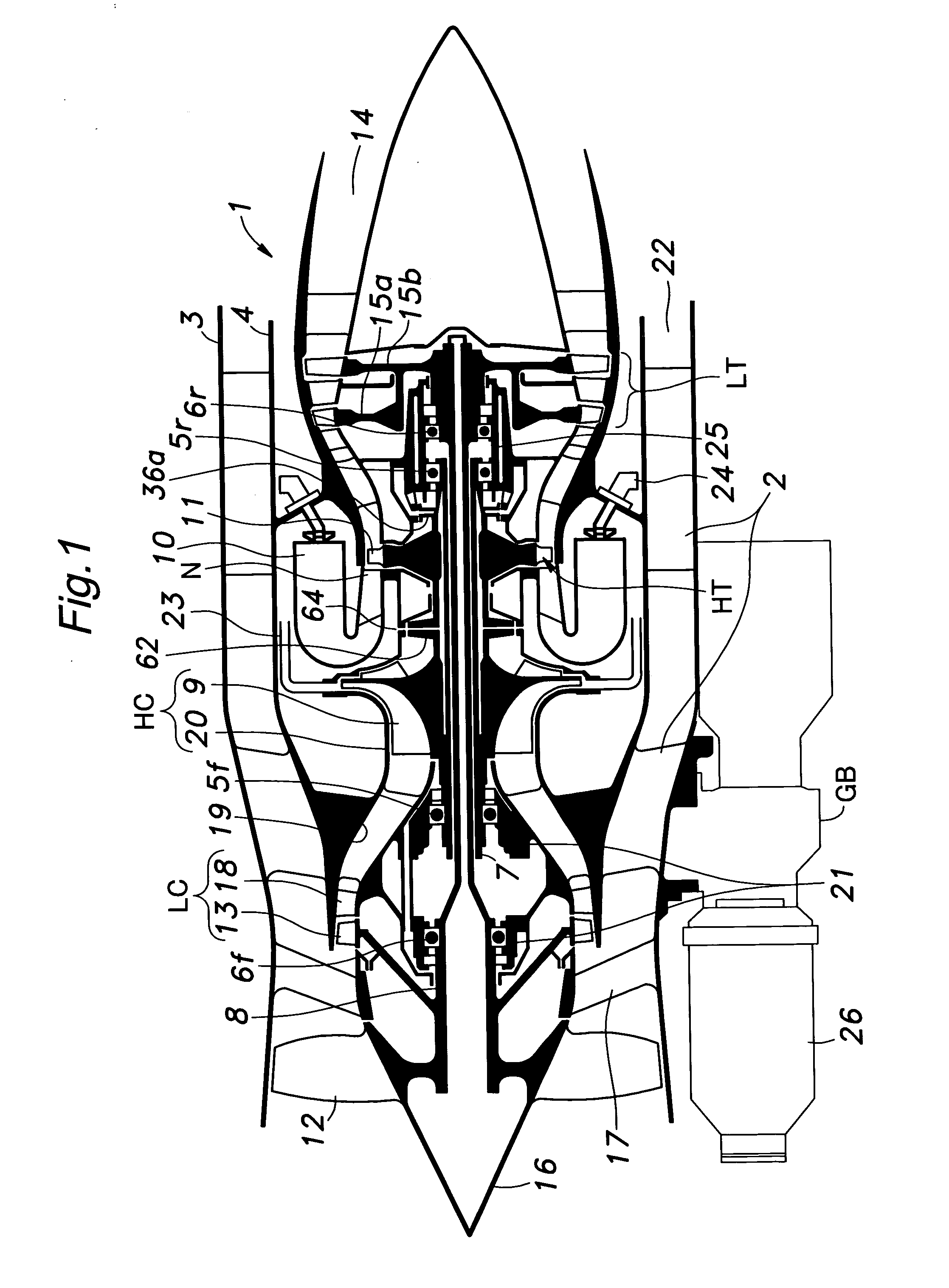
Figure 2 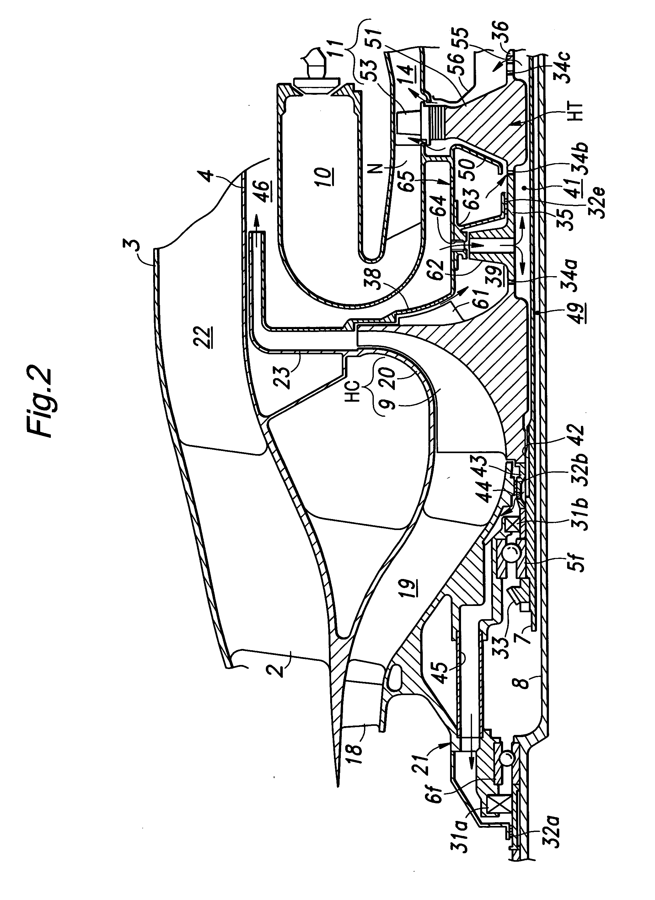
Figure 3
Abstract
Description
TECHNICAL FIELD
[0001] The present invention relates to a device for supplying secondary air in a gas turbine engine. BACKGROUND OF THE INVENTION
[0002] In a certain conventional gas turbine engine, an inner shaft supporting a low pressure compressor and a low pressure turbine and an outer shaft supporting a high pressure compressor and a high pressure turbine typically consist of hollow shafts which are coaxially nested with each other. Such a gas turbine engine is disclosed in the U.S. Pat. No. 5,862,666. According to the conventional gas turbine engine disclosed in this U.S. patent, the outer and inner shafts are supported by separate bearings at their front and rear ends, and each bearing is lubricated by a forced lubrication system which blows lubricating oil fed by a pump to the bearing.
[0003] In such a forced lubricating system, to positively prevent the lubricating oil from leaking out of the bearing boxes provided in the front and rear ends of the outer and inner shafts, h...
Examples
Embodiment Construction
[0030]FIG. 1 is a schematic view of a multiple shaft bypass jet engine embodying the present invention. This engine 1 comprises an outer casing 3 and an inner casing 4 consisting of coaxially arranged cylindrical members joined to each other by struts 2, and an outer shaft 7 and an inner shaft 8 consisting of coaxially arranged hollow shafts centrally supported in the casings by independent bearings 5f, 5r, 6f and 6r.
[0031] The outer shaft 7 has a front end (left end in the drawing) integrally carrying an impeller wheel 9 of a high pressure centrifugal compressor HC, and a rear end (right end in the drawing) integrally carrying a high pressure turbine wheel 11 of a high pressure turbine HT provided adjacent to nozzles N of counter-flow combustion chambers 10.
[0032] The inner shaft 8 has a front end integrally carrying a front fan 12 and a compressor wheel 13 supporting rotor vanes for a low pressure axial flow compressor LC immediately behind the front fan 12, and a rear end integ...