
Catoptric imaging systems comprising pellicle and/or aperture-array beam-splitters and non-adaptive and/or adaptive catoptric surfaces
Patent Information
- Authority / Receiving Office
- US · United States
- Current Assignee / Owner
- Publication Date
- 2006-03-30
- Estimated Expiration
- Not applicable · inactive patent
Smart Images
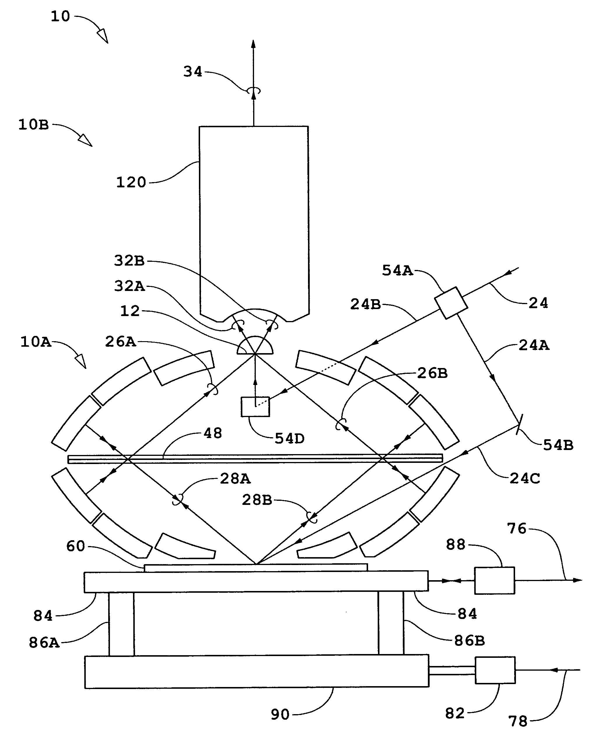
Figure 1 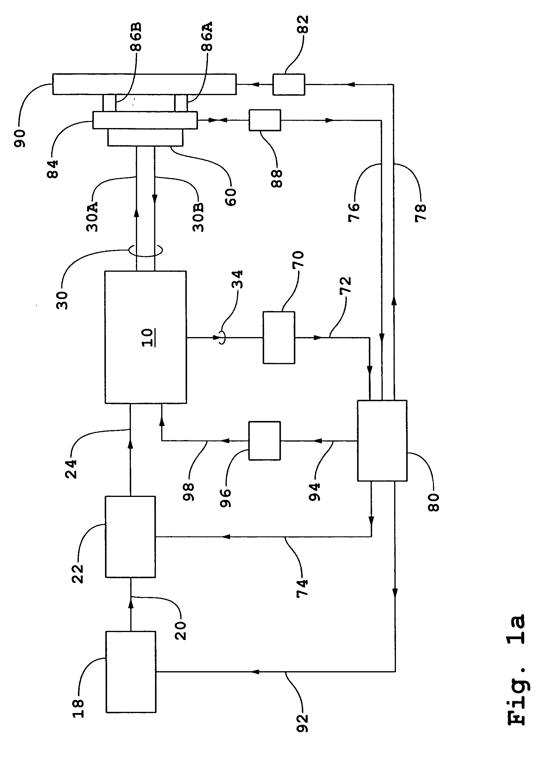
Figure 2 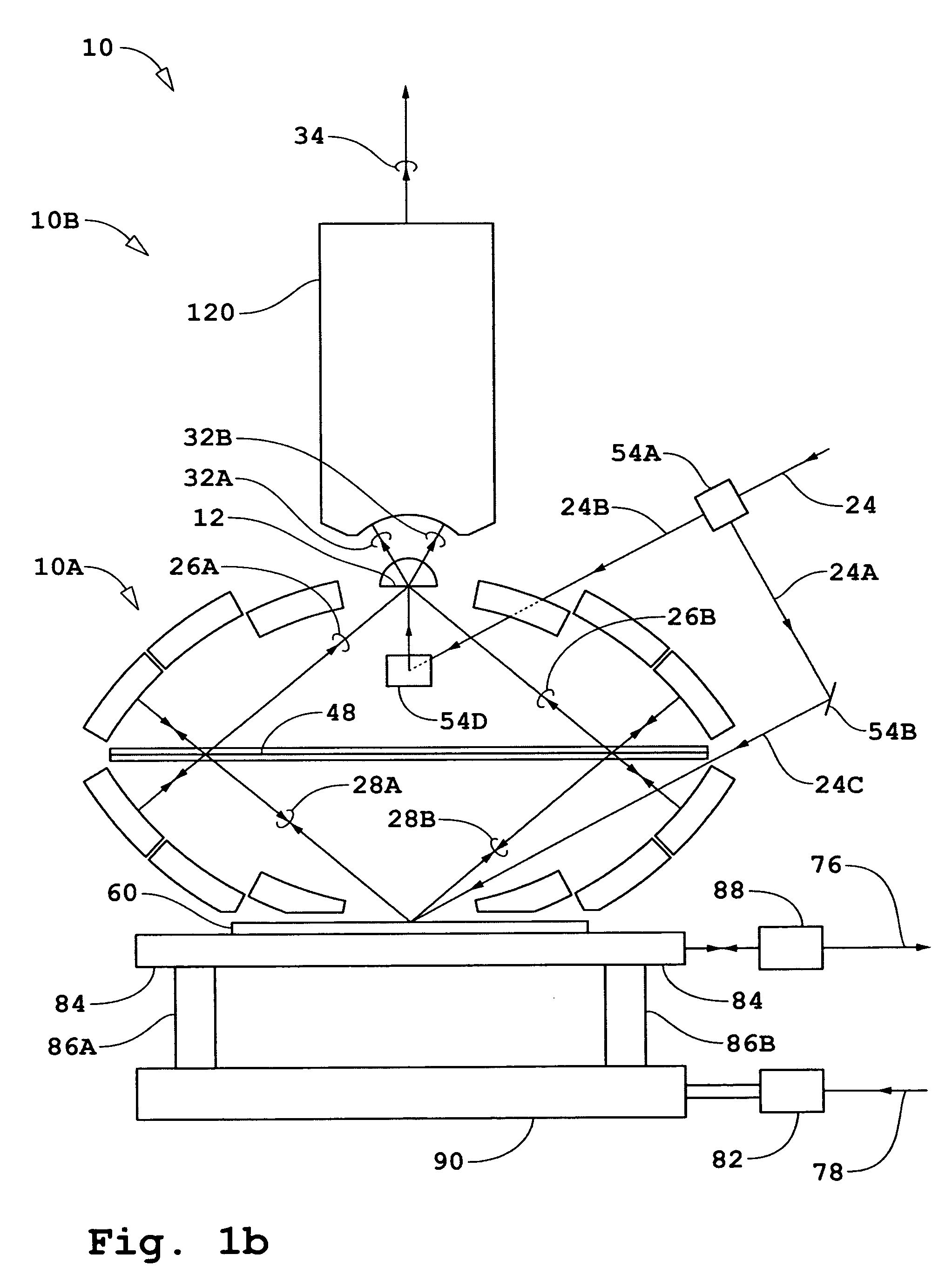
Figure 3
Abstract
Description
[0001] This application also claims the benefit of U.S. Provisional Application No. 60 / 611,564, filed Sep. 20, 2004, incorporated herein by reference. RELATED APPLICATIONS
[0002] The following applications are related to the present application: U.S. Pat. No. 6,552,852, issued Apr. 22, 2003 and entitled “Catoptric and Catadioptric Imaging Systems,” (ZI-38); U.S. Ser. No. 60 / 447,254, filed Feb. 13, 2003, and U.S. Ser. No. 10 / 778,371, filed Feb. 13, 2004, both of which are entitled “Transverse Differential Interferometric Confocal Microscopy,” (ZI-40); U.S. Ser. No. 60 / 448,360, filed Feb. 19, 2003, and U.S. Ser. No. 10 / 782,057, filed Feb. 19, 2004, both of which are entitled “Longitudinal Differential Interferometric Confocal Microscopy For Surface Profiling,” (ZI-41); U.S. Ser. No. 60 / 448,250, filed Feb. 19, 2003, and U.S. Ser. No. 10 / 782,058, filed Feb. 19, 2004, both of which are entitled “Method And Apparatus For Dark Field Interferometric Confocal Microscopy,” (ZI-42); U.S. Pat. ...
Examples
Embodiment Construction
[0072] A general description of embodiments incorporating the present invention will first be given for interferometer systems wherein either a N-dimensional bi- or quad-homodyne detection method is used where N is an integer. Referring to FIG. 1a, an interferometer system is shown diagrammatically comprising an interferometer 10, a source 18, a beam-conditioner 22, a detector 70, an electronic processor and controller 80, and a measurement object shown as substrate 60. Source 18 generates input beam 20. The interferometer system shown in FIG. 1a is for the case of an imaging system operating in a reflecting mode to measure properties of fields reflected / scattered by substrate 60. For the case of operation in a transmission mode, a portion of beam 24 split off as a measurement beam is incident on substrate 60 from the backside of substrate 60 such as shown diagrammatically in FIG. 2a. Source 18 is preferably a pulsed source that generates beam 20 with a single frequency component. B...