
Atmospheric pressure ionization mass spectrometer system
a mass spectrometer and atmospheric pressure technology, applied in the field of mass spectrometer systems, can solve the problems of shortcoming of reducing the efficiency of transporting ions, and achieve the effect of simple construction, effective space saving, and simple construction
Patent Information
- Authority / Receiving Office
- US · United States
- Patent Type
- Applications(United States)
- Current Assignee / Owner
- Publication Date
- 2006-06-15
Smart Images
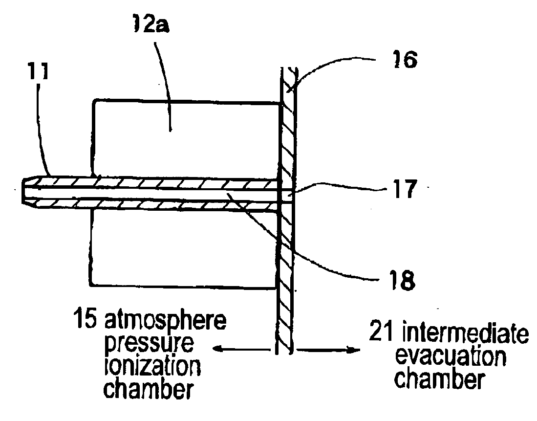
Figure 1 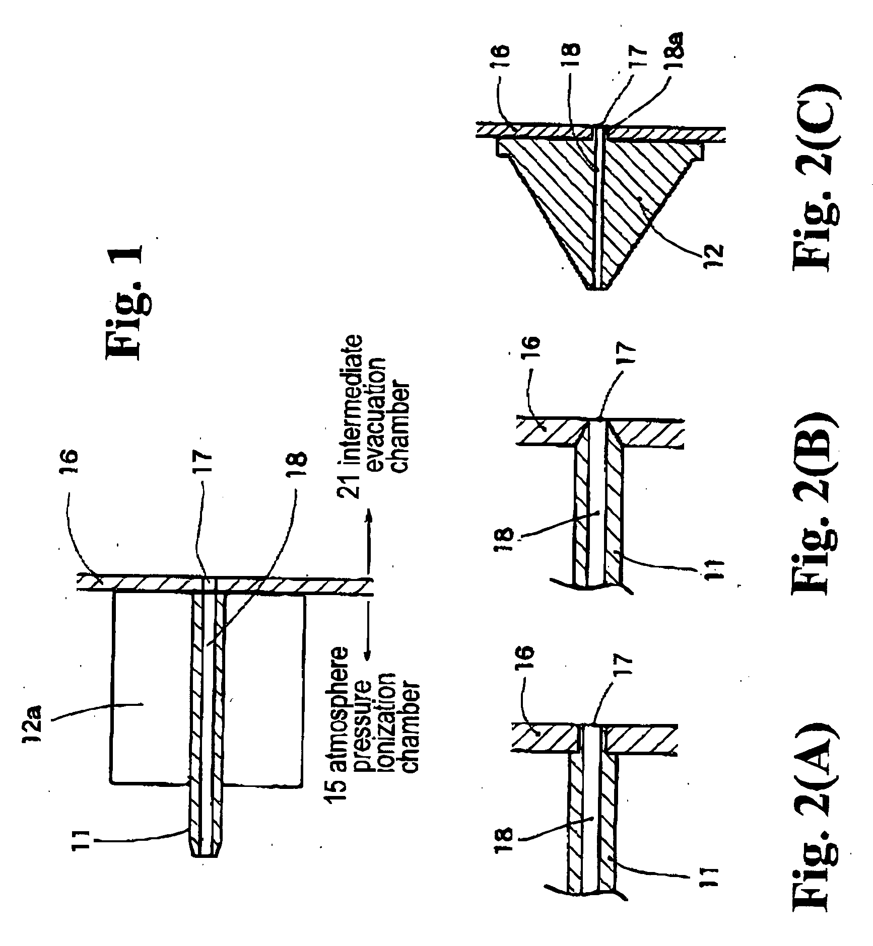
Figure 2 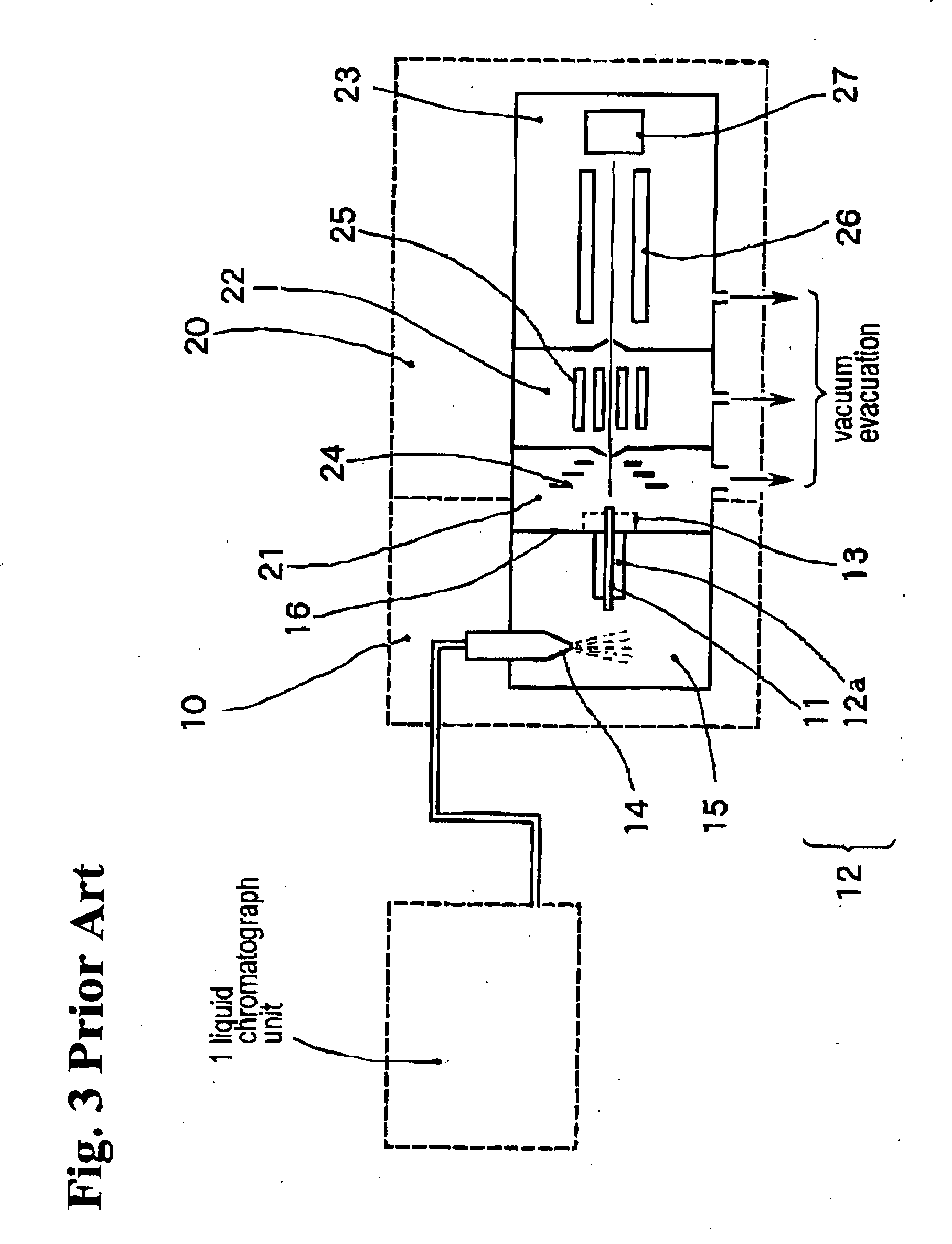
Figure 3
Abstract
Description
BACKGROUND OF THE INVENTION AND RELATED ART STATEMENT
[0001] The present invention relates to a mass spectrometer system that includes an atmospheric pressure ionization interface suited for use in combination with a liquid chromatograph, i.e., as a liquid chromatograph mass spectrometer.
[0002] A mass spectrometer (hereinafter referred to as “MS”) is occasionally used in combination with a liquid chromatograph, as a liquid chromatograph mass spectrometer (hereinafter referred to as LC / MS). In an LC / MS, the components of a sample separated by liquid chromatography are introduced into the MS for mass spectrometry. In order to perform mass spectrometry, an interface is required to ionize the separated components. In recent years, a method of performing ionization under atmospheric pressure, such as an electrospray interface or an atmospheric pressure chemical ionization interface, has been generally employed as the interface for an LC / MS.
[0003] The mass spectrometer located downstrea...
Examples
embodiment 1
[0026] The embodiment of the invention shown in FIG. 1 illustrates the basic construction of the present invention. FIGS. 2(A), 2(B), and 2(C) show several other embodiments of the present invention (described herein, respectively, as embodiments 1, 2, and 3), with various improvements for practical use.
[0027]FIG. 2(A) is an enlarged sectional view of the junction between the capillary tube 11 and the small orifice 17. The rear end section of the capillary tube 11 has reduced thickness, and is fitted into the small orifice 17. In this embodiment, the diameter of the small orifice 17 needs to be slightly larger than the inner diameter of the capillary tube 11. Since the inner wall of the small orifice 17 is covered, contamination of the inner wall can be prevented.
embodiment 2
[0028]FIG. 2(B) also shows the junction between the capillary tube 11 and the small orifice 17. In this second embodiment, the male taper formed in the rear end section of the capillary tube 11 mates with the female taper of the small orifice 17 formed so as to widen towards the atmospheric pressure ionization chamber 15. In this embodiment, the diameter of the small orifice 17 can be controlled to a size that is substantially equal to the inner diameter of the capillary tube 11, and the inner wall of the small orifice 17 is covered to protect against contamination.
[0029] In FIGS. 2(A) and (B), the heating block 12a is not depicted; it should be assumed, however, that the heating block 12a is fitted around the capillary tube 11, as in the case of FIG. 1.
embodiment 3
[0030]FIG. 2 (C) shows a third embodiment in which the capillary tube 11 is integrated with the heating block 12a to form a conical desolvating unit 12. That is, a conical block is formed with a material such as stainless steel, and the internal channel 18 is formed from the peak of the cone through the bottom surface along its axis. Such a construction is functionally equivalent to the aforementioned desolvating unit 12 composed by combining the capillary tube 11 and the heating block 12a. The rear end section of the internal channel 18 forms the projection 18a, which projects from the bottom surface of the cone in a distance corresponding to the thickness of the partition wall 16. The projection 18a is fitted into the small orifice 17 in the same manner as in the embodiment of FIG. 2(A) so as to cover the inner wall of the small orifice 17.
[0031] The projection 18a may be a male taper to be mated with the female taper of the small orifice 17, as in the case of FIG. 2(B).
[0032] M...