
High efficiency inductor, method for manufacturing the inductor, and packaging structure using the inductor
a high-efficiency inductors and manufacturing method technology, applied in the field of inductors, can solve the problems of difficulty in incorporating a device packaging, low quality factor of conventional inductors, and difficulty in manufacturing other devices together, and achieve excellent properties
Patent Information
- Authority / Receiving Office
- US · United States
- Current Assignee / Owner
- Publication Date
- 2007-04-19
Smart Images
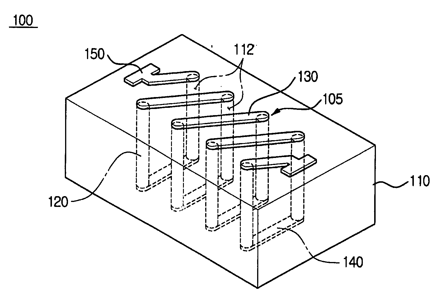
Figure 1 
Figure 2 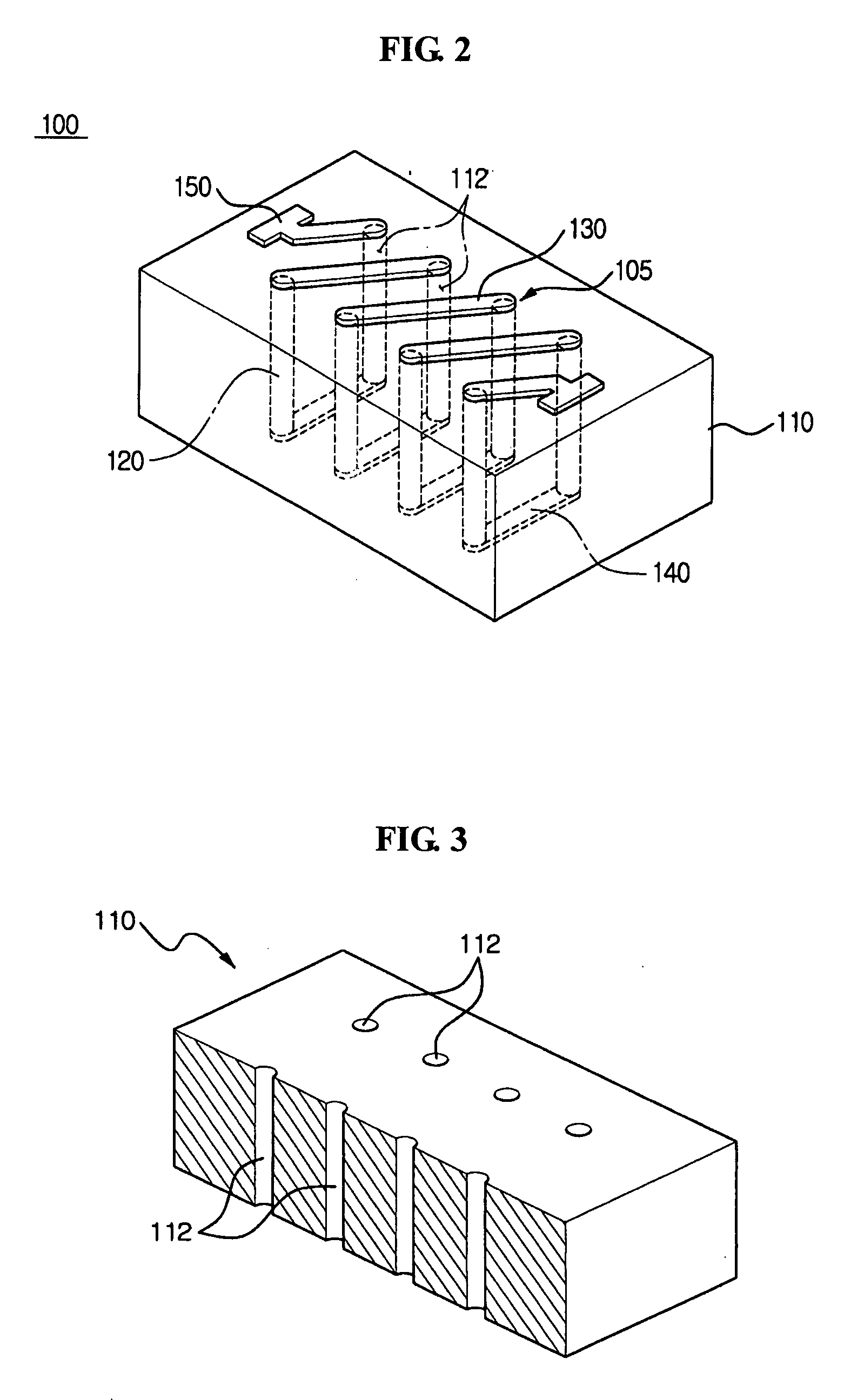
Figure 3
Abstract
Description
CROSS-REFERENCE TO RELATED APPLICATIONS
[0001] This application claims priority from Korean Patent Application No. 10-2005-98595, filed on Oct. 19, 2005, in the Korean Intellectual Property Office, the disclosure of which is incorporated herein in its entirety by reference. BACKGROUND OF THE INVENTION
[0002] 1. Field of the Invention
[0003] The present invention relates to an inductor, and more particularly, to a spiral inductor having a micro size and high efficiency, a method of manufacturing the inductor, and a device package structure using the inductor as a packaging element.
[0004] 2. Description of the Related Art
[0005] An inductor is one of the most important components forming an electric circuit, along with a resistor, a condenser, an electron tube, a transistor, and a power source, and has a coil structure in which copper or aluminum is wound in the shape of a screw several times. The inductor can suppress a sudden change of a current by inducing voltage in proportion to...
Examples
Embodiment Construction
[0031] Reference will now be made in detail to the exemplary embodiments of the present invention, examples of which are illustrated in the accompanying drawings, wherein like reference numerals refer to the like elements throughout. The exemplary embodiments are described below to explain the present invention by referring to the figures.
[0032]FIG. 2 is a perspective view illustrating an inductor 100 according to an exemplary embodiment of the present invention.
[0033] Referring to FIG. 2, the inductor 100 includes a substrate 110, vertical conductive portions 120, first horizontal conductive portions 130, second horizontal conductive portions 140, and electrode portions 150. The vertical conductive portions 120 pass through the body of the substrate 110 and are exposed at the top and the bottom of the body of the substrate 110. The first and second horizontal conductive portions 130 and 140, respectively, electrically connect the exposed vertical conductive portions 120 to provid...