
Surface Magnet Type Motor, Fabrication Method Of Surface Magnet Type Motor, And Internal Combustion Engine With Surface Magnet Type Motor
a technology of surface magnets and fabrication methods, applied in the direction of mechanical energy handling, stator/rotor bodies, applying solid insulation, etc., can solve problems such as the possibility of magnet fracture, and achieve the effect of preventing magnet scattering and being durable enough
Patent Information
- Authority / Receiving Office
- US · United States
- Patent Type
- Applications(United States)
- Current Assignee / Owner
- Publication Date
- 2008-05-15
Smart Images
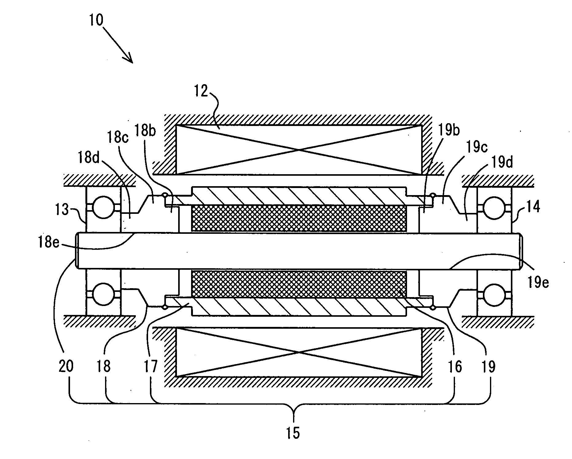
Figure 1 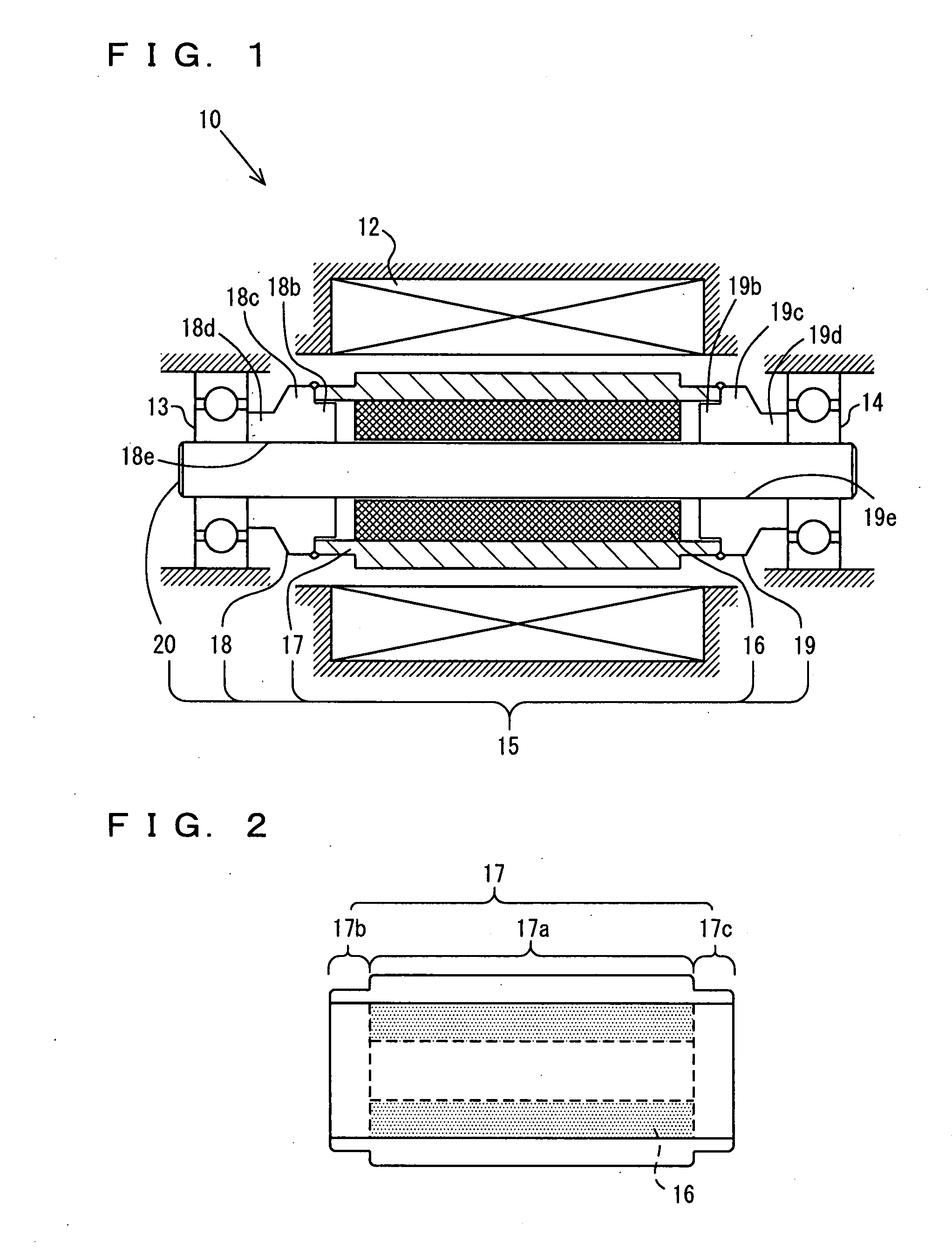
Figure 2 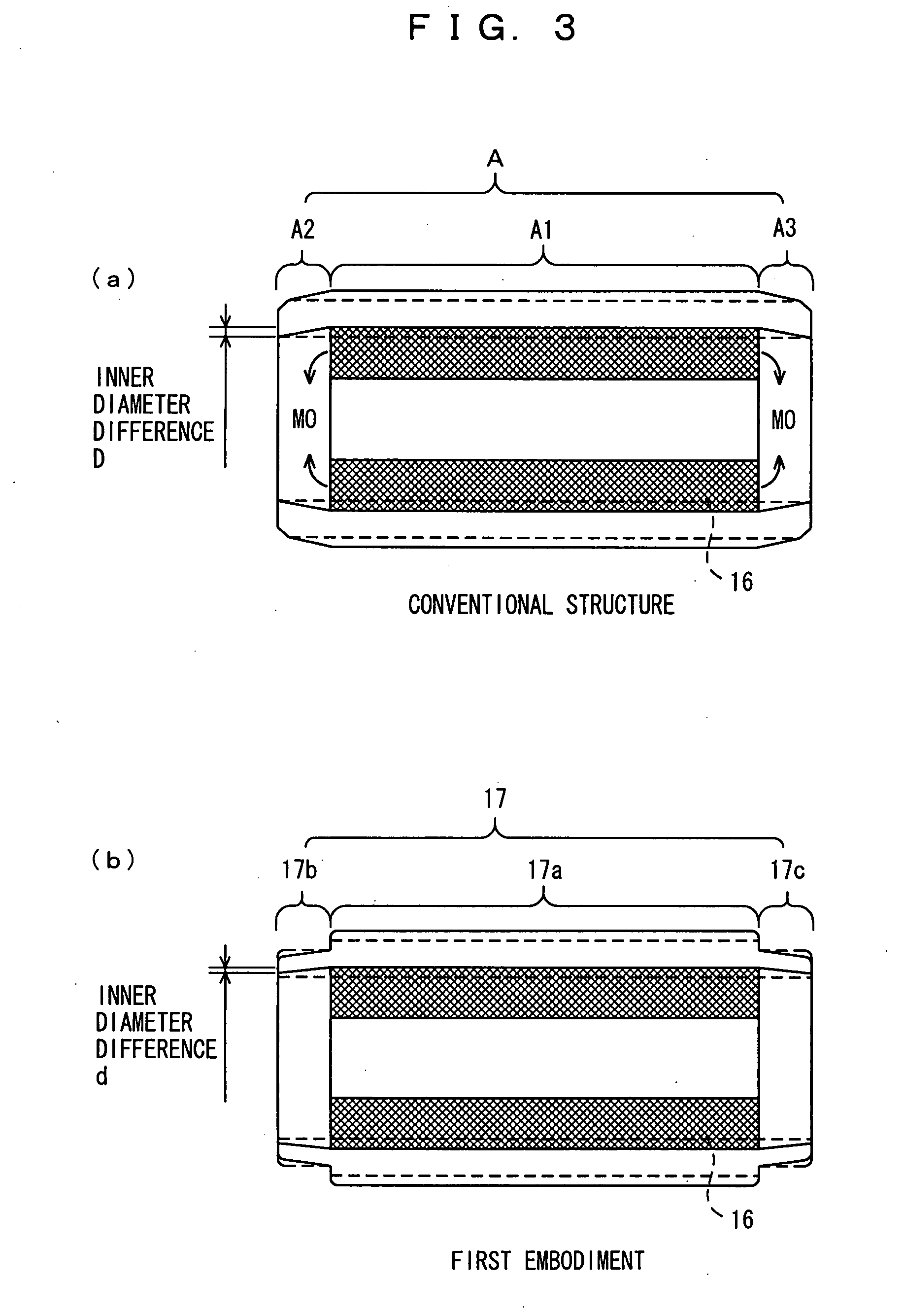
Figure 3
Abstract
Description
TECHNICAL FIELD
[0001] The present invention relates to a surface magnet type motor employing a magnet for the rotor, particularly to an anti-scattering tube for preventing scattering of the magnet.BACKGROUND ART
[0002] Conventionally, there is known a surface magnet type motor including a rotor having a magnet arranged at the outer circumferential surface of the rotational shaft. This type of motor is provided with a non-magnetic anti-scattering tube at the circumference of the magnet to prevent fracture and scattering of the magnet caused by the centrifugal force when the rotor rotates at high speed.
[0003] The anti-scattering tube of the motor is generally fixed by press-fitting the magnet into the inner cylinder of the anti-scattering tube. Accordingly, the magnet is firmly maintained with force to prevent fracture and scattering of the magnet caused by centrifugal force (for example, refer to Japanese Patent Laying-Open Nos. 2001-025193 and 2001-218403).
[0004] In order to realize usag...
Examples
first embodiment
[0084]Rotational shaft 20 of the assembled rotor 15 has bearings 13 and 14 attached. For bearings 13 and 14, a ball bearing having low rotation resistance is employed to take a structure that can withstand even high speed rotation. By mounting rotor 15 with bearings 13 and 14 attached in a housing of motor 10 including stator 12, electric motor 10 is implemented. The current flow to the coil of stator 12 is supplied from an electric circuit (refer to FIG. 18).[0085]A-1. First Embodiment of Anti-Scattering Tube:
[0086]FIG. 2 is a sectional view of a structure of anti-scattering tube 17 of the first embodiment into which magnet 16 is press-fitted. As shown in the drawing, anti-scattering tube 17 made of titanium is formed in a step-graded cylindrical configuration longer in length than magnet 16. Magnet 16 is located in the proximity of approximately the center of the step-graded cylindrical configuration. This anti-scattering tube 17 is mainly formed of three portions, i.e. a cylinder...
second embodiment
[0092]FIG. 4 shows an example of an anti-scattering tube including a projection portion of low rigidity. As shown in the drawing, an anti-scattering tube 27 has a cylindrical configuration substantially similar to that of anti-scattering tube 17 of FIG. 2, and differs only in the configuration of projection portions 27b and 27c protruding from the end face of press-fitted magnet 16. Projections 27b and 27c of anti-scattering tube 27 has a groove corresponding to a notch of a predetermined width and predetermined depth over the entire perimeter. By providing such notches, similar advantages can be provided even with projection portions 27b and 27c of low rigidity. Furthermore, projection portions 27b and 27c of low rigidity can be formed by a relatively simple process.[0093]A-2. Second Embodiment of Anti-Scattering Tube:
[0094]The first embodiment is directed to suppressing the inner diameter difference by forming projection portions 17b and 17c in a configuration of low rigidity. How...
third embodiment
[0111]Salient 57a provided only on the part of anti-scattering tube 57 may be provided only on the part of assembly flange 48, as shown in FIG. 12. In this case, a salient 48a is provided at assembly flange 48, as shown in the drawing. It is not necessary to provide a particular configuration for the anti-scattering tube, as compared to the structure shown in FIG. 10.[0112]B-3. Third Embodiment of Contact Portion Structure:
[0113]FIG. 13 is a partial sectional view of a structure of a contact portion of the assembly flange and anti-scattering tube according to a third embodiment. Although only the bearing 13 side is indicated as the contact portion structure in FIG. 13, a contact portion structure symmetric to the bearing 13 side is provided at the bearing 14 side, likewise FIG. 10.
[0114]As shown in the drawing, the contact portion of anti-scattering tube 67 includes a tapered portion 67a having the inner diameter increased in the direction from the end face of magnet 16 to the end f...