
Drill Hammer With Three Modes of Operation
a drill hammer and three-mode technology, applied in the field of drill hammer, can solve the problems of increased structural length, increased structural volume and mass, heat development, wear, etc., and achieves the effect of improving the efficiency of the drill hammer, reducing friction losses, and reducing the length of the structur
Patent Information
- Authority / Receiving Office
- US · United States
- Patent Type
- Applications(United States)
- Current Assignee / Owner
- Publication Date
- 2008-07-17
Smart Images
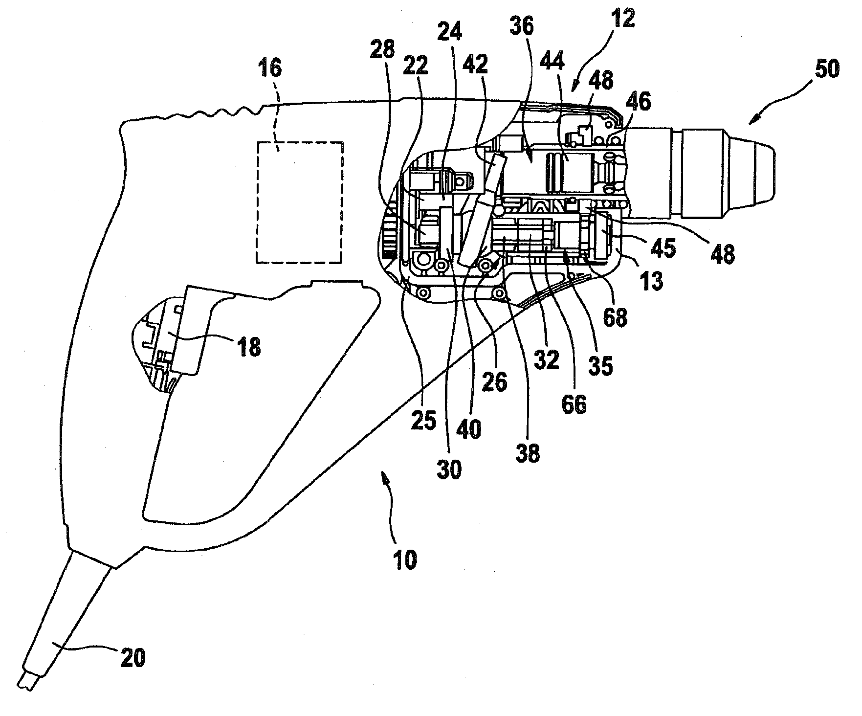
Figure 1 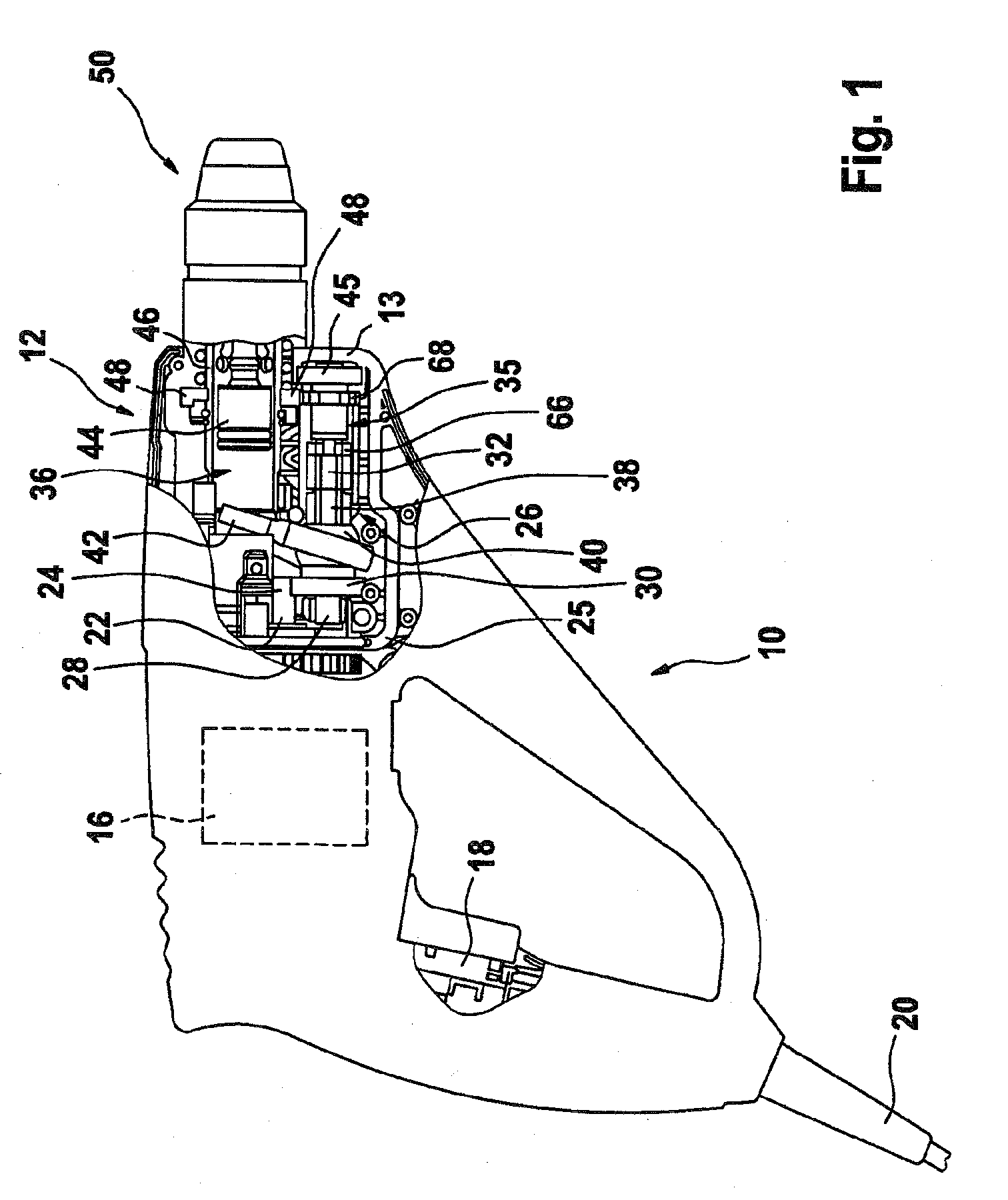
Figure 2 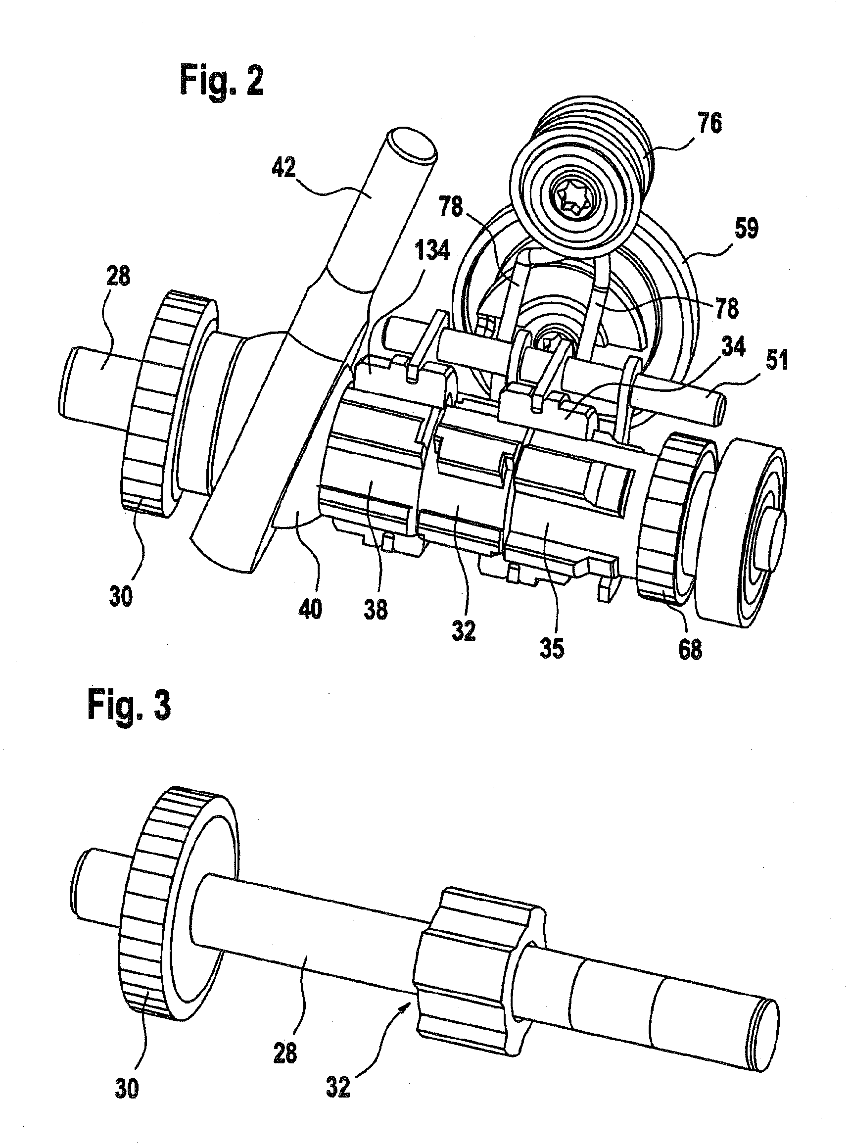
Figure 3
Abstract
Description
PRIOR ART
[0001] The present application is based on a drill hammer as generically defined by the preamble to claim 1.
[0002] From Japanese Patent Application JP 9-272005, a drill hammer with a changeover mechanism for the three modes of operation of drilling, chiseling, and hammer-drilling is known. The drill hammer has an electric motor, which via a motor pinion meshes with a drive pinion of an intermediate shaft. The drive pinion is seated, in a manner fixed against relative rotation, on the intermediate shaft and transmits the rotary motion of the motor to the intermediate shaft. A toothed slaving shaft is also seated, approximately centrally, on the intermediate shaft in a manner fixed against relative rotation.
[0003] A drive bearing for a hammering percussion mechanism is seated, rotatably and rotationally lockably, on the intermediate shaft, axially adjacent to the first side of the toothed slaving shaft. With it, the rotation of the intermediate shaft can be converted into an axi...
Examples
Embodiment Construction
[0035]FIG. 1 shows a drill hammer 10 with a housing 12, which comprises two half-shells 13, 14 of plastic with a vertical parting line, with the upper half-shell 14 removed. The lower half-shell 13 with the functional parts located in it is therefore visible.
[0036]The housing 12 receives a motor 16 with an on-off switch 18 and a 30 corresponding power cord 20 for connection to an external source of current, as well as a gear 26 and a percussion mechanism 36. The motor 16 includes a motor shaft 22, whose free end has a motor pinion 24 that is supported in an intermediate flange 25 that can be positionally secured between the half-shells 13, 14. The motor pinion 24 is in engagement with a driving gear wheel 30 of an intermediate shaft 28 of the gear 26 that is supported by one end in the intermediate flange 25, via a needle bearing, not shown. Adjoining this, adjacent to the driving gear wheel 30 that is firmly seated on the intermediate shaft, in particular pressed onto it, a wobble ...