

Interchangeable Power Plant for Automobiles
a technology of hybrid electric vehicles and power plants, applied in the direction of electric propulsion mounting, roofs, transportation and packaging, etc., can solve the problems of 3) time taken to recharge batteries, 4) cost of rechargeable batteries, and establishing one will be very expensiv
Patent Information
- Authority / Receiving Office
- US · United States
- Current Assignee / Owner
- Publication Date
- 2009-04-23
- Estimated Expiration
- Not applicable · inactive patent
Smart Images
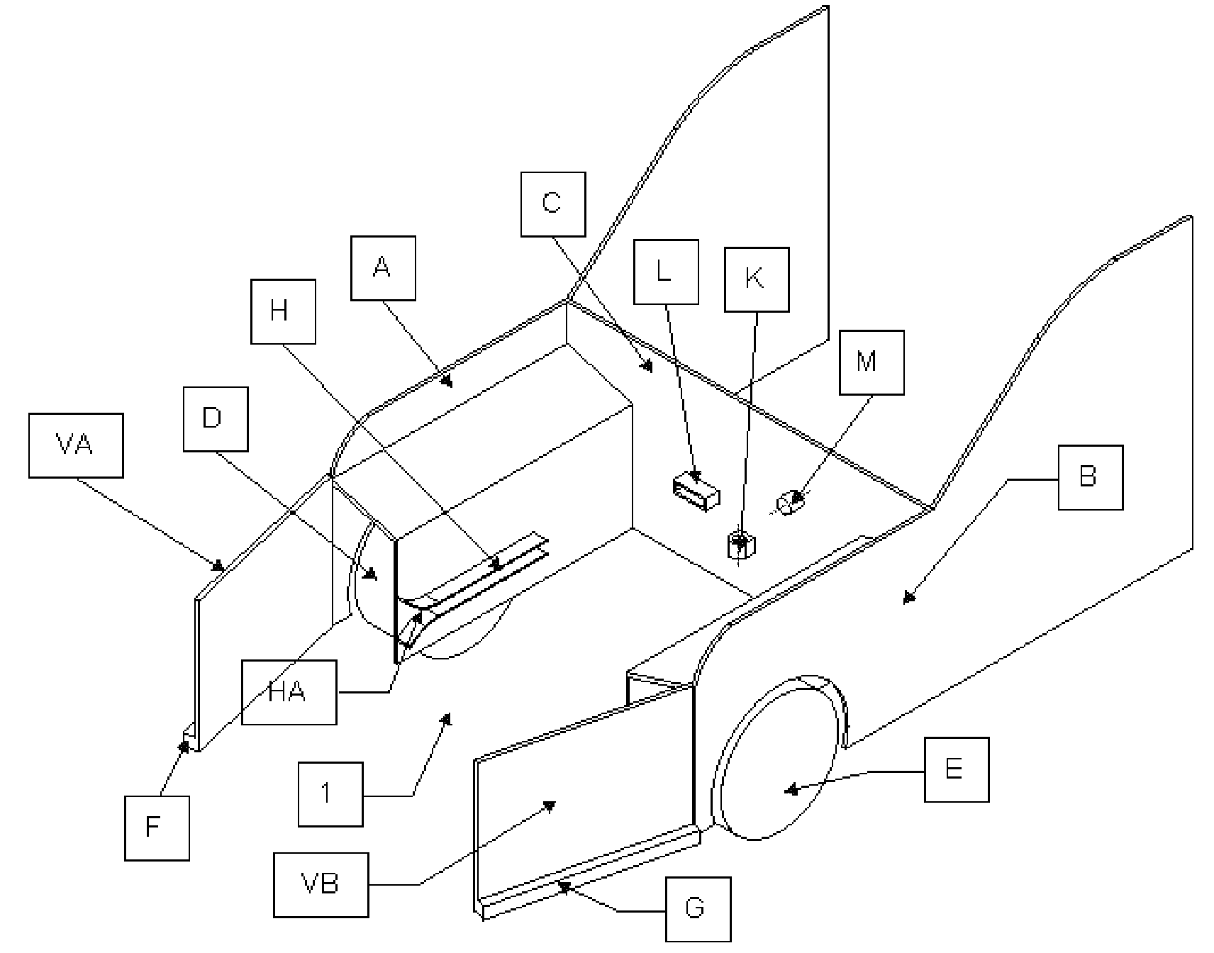
Figure 1 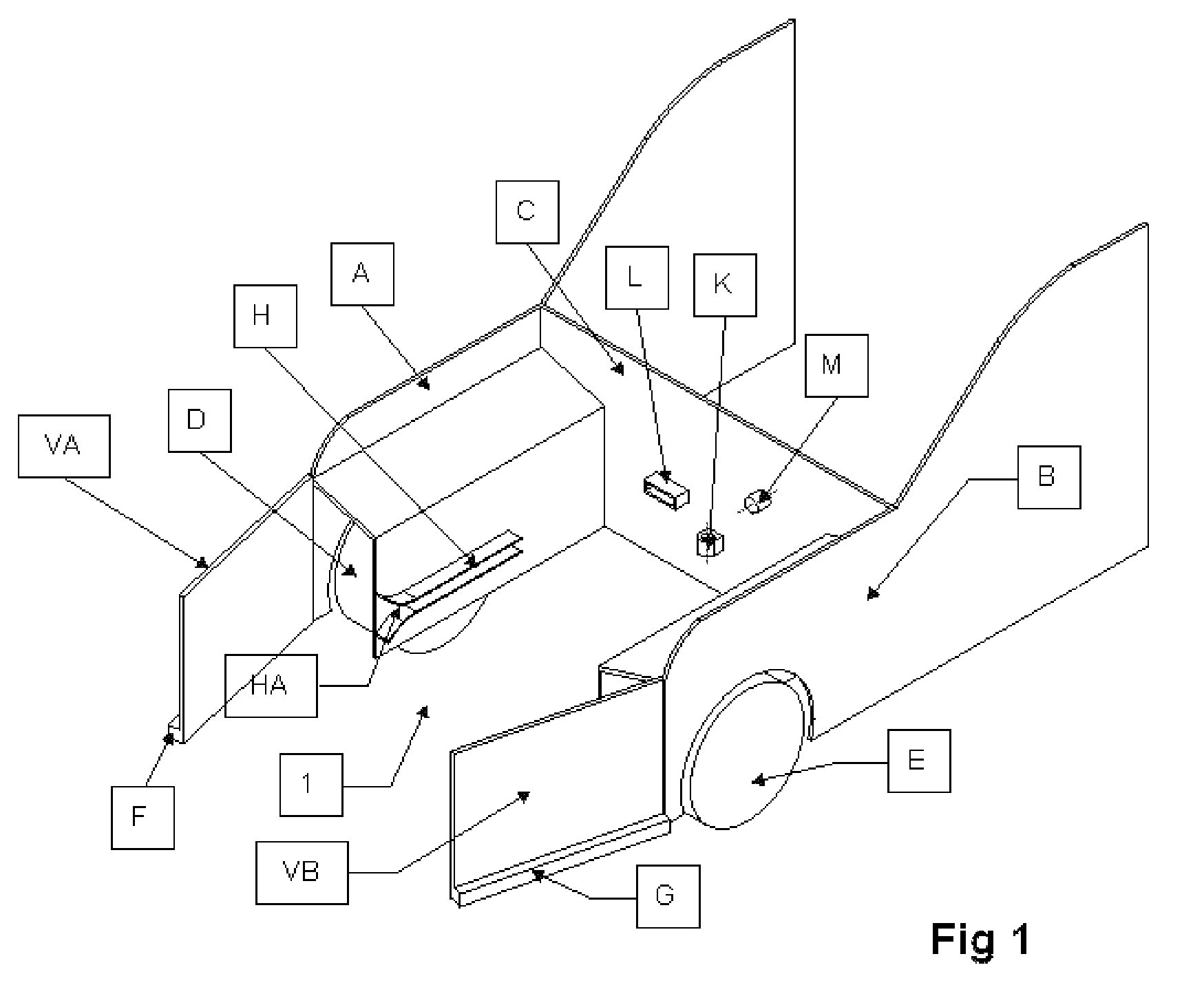
Figure 2 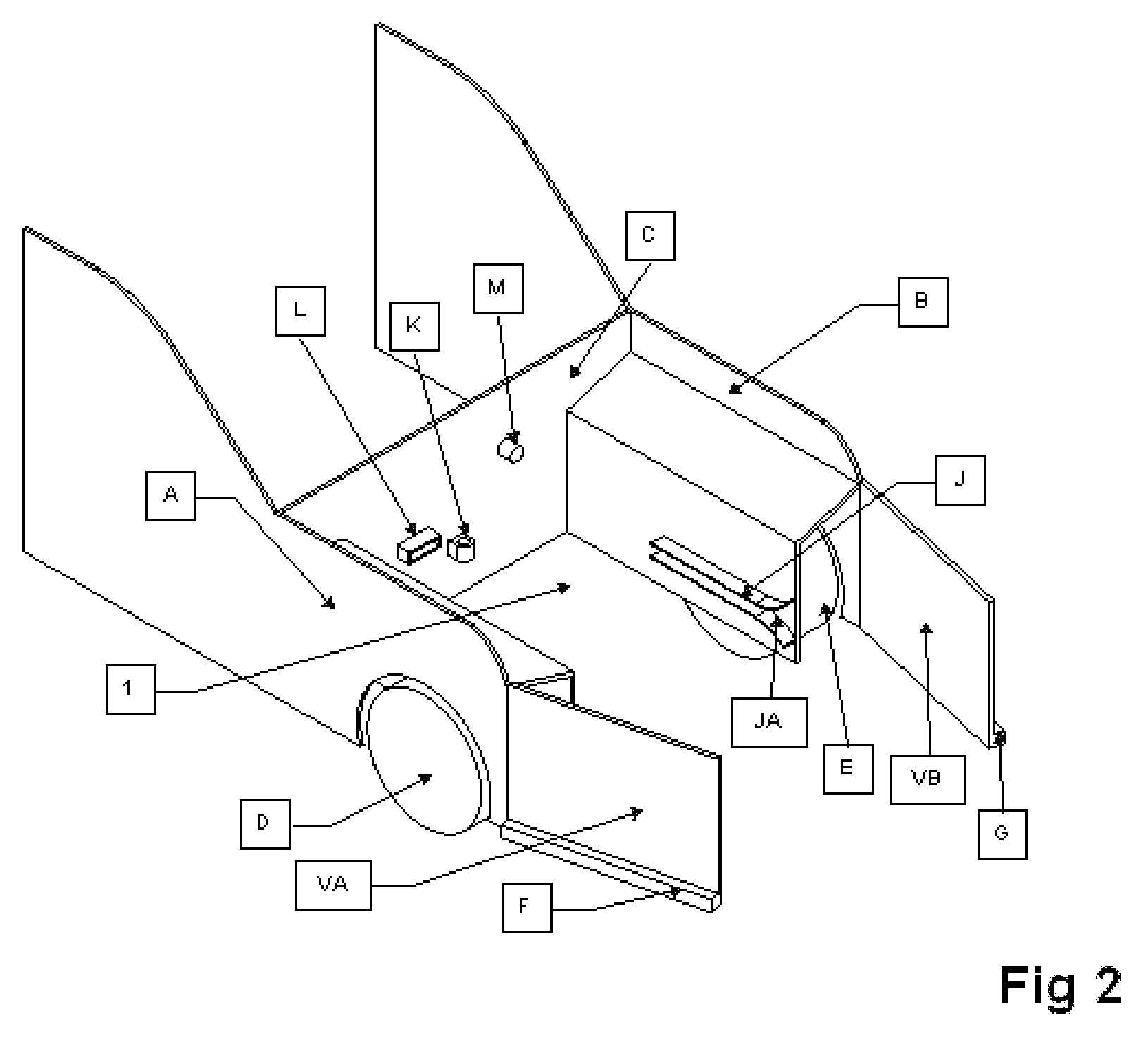
Figure 3
Abstract
Description
CROSS REFERENCE TO RELATED APPLICATIONS
[0001] This patent application claims priority from provisional U.S. patent application entitled “Interchangeable Power Plant for Automobiles,” having application No. 60 / 971,405 filed on Sep. 11, 2007, the contents of which are incorporated herein by reference.REFERENCE CITED
[0002] U.S. Pat. No. 5,760,569—Jun. 2, 1998—Chase Jr., Robert B.U.S. Pat. No. 5,251,721—Oct. 12, 1993—Ortenheim, Bjorn A.FIELD OF INVENTION
[0003] The present invention relates generally to hybrid electric vehicles that use one or more power sources to propel a vehicle. The common sources of power are the battery and the internal combustion engine. The present invention relates more particularly to methods and systems to build a vehicle in which the power plants can be changed quickly.BACKGROUND OF INVENTION
[0004] In the United States, people generally drive about 30 to 60 miles per day to get to work and back. In many other countries, the distances are much less. But the manufa...
Examples
Embodiment Construction
[0018]Referring to FIG. 1 and FIG. 2, the whole chamber is generally referred to as 1. Chamber 1 has a left side wall A; a right side wall B and a back wall C, together forming an enclosure for the power plant. The front wheels of the vehicle are marked D and E. The vehicle has a left front fender, F, and a right front fender, G. Fender F is connected to the left side wall A with hinges. Similarly, fender G is connected to the right side wall B with hinges. Fenders F and G meet at the center. Side walls A and B have guide rails, H and J on their inside surface. Guide rail H is mounted horizontally along the length of side wall A. Similarly, guide rail J is mounted horizontally along the length of side wall B. The guide rails have a latch such that when the power plant is pushed all the way in toward the back wall C, it will lock the power plant on the rails, thus preventing it from sliding out. The latch must be released manually to slide the power plant out. An engine mount, K, is ...